


Troubleshooting and Problem Solving
IBM System Storage DCS9550 1S1 Storage Expansion Unit Installation, Service, and User Guide 41
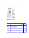
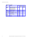
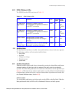
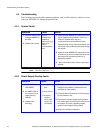
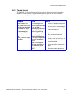
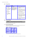
4.3.3 SCM I/O Module LEDs
The SCM I/O module LEDs are shown in Table 4–3.
4.4 Audible Alarm
The Ops Panel also includes an Audible Alarm which indicates when a fault state is present.
The following conditions will activate the Audible Alarm:
• Drive Fault
• Fan Fault
• Voltage out of range
• Thermal overrun
•System fault
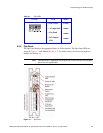
4.4.1 Audible Alarm Mute
When the Audible Alarm sounds, it may be muted by pressing the Alarm Mute push-button.
Automatic muting will take place after two minutes if the mute switch is not manually
operated. The Alarm Mute push-button is located above the indicators on the Ops Panel (see
Figure 4–1). When the alarm is muted, it will continue to sound with short intermittent bleeps
to indicate that a problem still exists. It will be silenced when all problems are cleared. (See
also Thermal Shutdown states, Section 4.5.5).
LED Test Mode
The Alarm Mute push-button can also be used to test the LEDs on the Ops Panel. When the
Mute push-button is held, all LEDs will be illuminated if there are no faults present.
Table 4–3 SCM I/O Module LEDs
LED Definition Color Normal
Status
Fault
Status
FC Host Port 0
Signal Good
Incoming FC signal is GOOD
No connection or incorrect connection
Invalid SFP connection
Green On
Off
Flashin
g
FC Host Port 1
Signal Good
Incoming FC signal is GOOD
No connection or incorrect connection
Invalid SFP connection
Green On
Off
Flashin
g
Router Status Storage Router Device Ready
Storage Router Device not ready or
defective
Green On
Off
ESI/SCM
Module Fault
Fault present (also On when booting)
Successful controller initialization
Amber On
Off