


Troubleshooting and Problem Solving
50 IBM System Storage DCS9550 1S1 Storage Expansion Unit Installation, Service, and User Guide
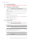
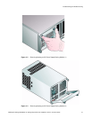
4.9.3.2 Inserting the Module
ATTENTION If only one SCM module is fitted, it must be installed in Module B location
(Rear Bay 4) [see Figure 2–1, ”Module locations”, on page 16] and an I/O
blank module fitted in the unused bay.
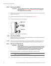
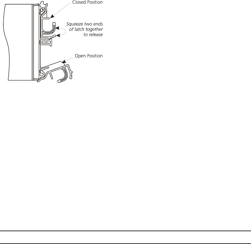
1 With the latch in the open position, slide the SCM I/O module into the enclosure until the latch
engages automatically.
2 Cam the module home by manually closing the latches (see Figure 4–7).
3 A click should be heard as the latch engages.
4.9.4 Drive Carrier Module
Please see section 2.9 for information on the initial installation of the plug-in modules in the
DCS9550 1S1 Storage Expansion Unit.
Caution Observe all conventional ESD precautions when handling the DCS9550 1S1 Storage Expansion Unit
modules and components. Avoid contact with backplane components and module connectors, etc.
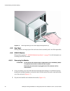
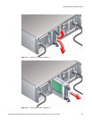
4.9.4.1 Removal and Replacement
ATTENTION Drive spin down
Damage can occur to a drive if it is removed while still spinning. If possible
use the operating system to spindown the drives prior to removal. If this is
not possible we recommend that you perform All steps of the following
procedure to ensure that the drive has stopped prior to removal:
1 Release the carrier handle, by pressing the latch in the handle towards the right
Note The anti-tamper lock must be off.
2 Gently withdraw the Drive Carrier Module approximately1 inch (25mm) and wait 30 seconds.
Figure 4–7 SCM I/O Module Latch Operation