


Introduction
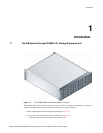
IBM System Storage DCS9550 1S1 Storage Expansion Unit Installation, Service, and User Guide 9
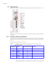
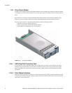
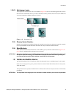
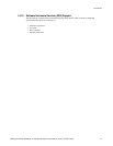
1.2.4.3 Anti-tamper Locks
Anti-tamper locks are fitted in the drive carrier handles (Figure 1–10) and are accessed through the small cutout in
the latch section of the handle.These are provided to disable the normal ‘pinch' latch action of the carrier handle and
so prevent accidental or unauthorized removal of drives.
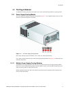
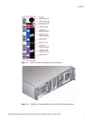
1.2.5 Dummy Carrier Modules
Dummy carrier modules are provided for fitting in all unused drive bays. They are designed as integral drive module
front caps with handles and must be fitted to all unused drive bays to maintain a balanced airflow.
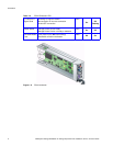
1.2.6 Blank Modules
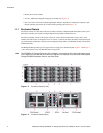
Blank SCM I/O modules must be fitted in the vacant SCM bay (slot 3) at the rear of the enclosure (Figure 1–3 on
page 2 refers) to maintain airflow and ensure correct operation.
ATTENTION Operation of the Enclosure with ANY modules missing will disrupt the airflow and the drives will
not receive sufficient cooling. It is ESSENTIAL that all apertures are filled before operating the
unit. Dummy Carriers and/or Blank modules are available for this purpose.
1.3 Visible and Audible Alarms
The functional modules have associated status LEDs. The Ops Panel shows a consolidated status for all modules.
LEDs show constant green for good or positive indication. Constant Amber LEDs indicate there is a fault present
within that module.
The Ops Panel also incorporates an Audible Alarm to indicate when a fault state is present and also an Alarm Mute
push-button.
ATTENTION The Ops Panel is an integral part of the enclosure chassis assembly and is not field replaceable.
Figure 1–10 Anti-tamper Lock