


Installation
IBM System Storage DCS9550 1S1 Storage Expansion Unit Installation, Service, and User Guide 15
2
Installation
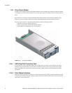
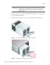
In this chapter, you are shown how to install your DCS9550 1S1 Storage Expansion Unit and
plug-in modules into an industry standard 19 inch rack cabinet.
Caution When connecting up the DCS9550 1S1 Storage Expansion Unit, use only
the power cords supplied or cords which match the specification quoted in
section 1.4.5.
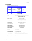
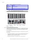
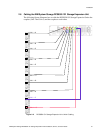
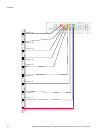
2.1 Planning Your Installation
Before you begin installation you should become familiar with the configuration requirements
of your DCS9550 1S1 Storage Expansion Unit, detailed in Table 2–1. The correct positions of
each of the optional plug-in modules are shown in Table 2–1. Please refer to sections 2.4 - 2.7
for details of SCM I/O module configurations and installation.
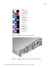
Table 2–1 DCS9550 1S1 Storage Expansion Unit Configuration
Module Location
Drive Bays ALL drive bays must be fitted with either a drive carrier module
or a dummy carrier, no bays should be left completely empty.
Drive carrier modules 0 & 15 provide SES Management Services.
Power Supply/
Cooling Modules
Two Power Supply/Cooling modules must be fitted. Full power
and cooling redundancy is provided while a faulty module is
replaced. Install the Power Supply/Cooling modules in rear Bays
1 and 5.
Note: Rear bays are numbered from 1 to 5 commencing from the right
side.
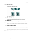
SCM I/O Module One SCM module should be installed in rear Bay 3. A blank
module is fitted rear Bay 4.