


Installation
16 IBM System Storage DCS9550 1S1 Storage Expansion Unit Installation, Service, and User Guide
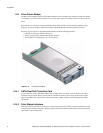
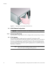
Caution Dummy Carriers and Blank Modules MUST be fitted to ALL unused bays.
There is inadequate drive cooling if any are left open.
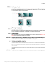
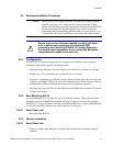
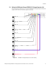
2.1.1 Enclosure Bay Numbering Convention
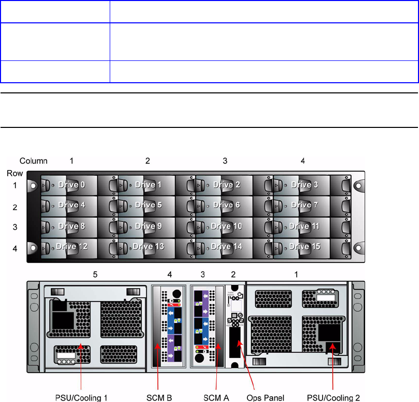
The enclosure bay numbering convention is shown in Figure 2–1. A bay is defined as the space
required to house a single 1.0 inch high 3.5 inch disk drive in its carrier module. For example,
a 1 x 4 bay module would take the space of 1 drive width by 4 drive bays high (in the rack
mount configuration).
The DCS9550 1S1 Storage Expansion Unit is housed in a 4 x 4 enclosure, that is, 4 bays wide
by 4 bays high.
• The front bays are numbered 1 to 4 from left to right, as viewed from the front. Bays are
numbered from 1 (top row) to 4 (bottom row). Drive Carrier Module locations are
identified from a matrix of the top and side numbers.
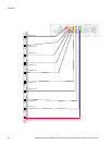
• The rear bays are numbered 1 to 5 from right to left, as viewed from the rear.
Blank SCM I/O
Modules
Install in rear Bay 4.
Ops Panel (integral part of chassis assembly). Installed in rear Bay 2.
Figure 2–1 Module locations
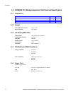
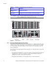
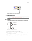
Table 2–1 DCS9550 1S1 Storage Expansion Unit Configuration
Module Location