


EM78P221/2N
8-Bit Microcontroller with OTP ROM
10 •
Product Specification (V1.0) 10.19.2007
(This specification is subject to change without further notice)
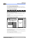
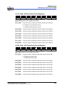
"JMP" instruction allows direct loading of the lower 10 program counter bits. Thus,
"JMP" allows PC to jump to any location within a Page (1K).
"CALL" instruction loads the lower 10 bits of the PC, and then PC+1 is pushed into the
stack. Thus, the subroutine entry address can be located anywhere within a page (1K).
"LJMP" instruction allows direct loading of the lower 11 program counter bits.
Therefore, "LJMP" allows PC to jump to any location within 2K (2
12
).
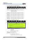
"LCALL" instruction loads the lower 11 bits of the PC, and then PC+1 are pushed onto
the stack. Thus, the subroutine entry address can be located anywhere within 2K (2
12
).
"RET" ("RETL k", "RETI") instruction loads the program counter with the contents of the
top of stack.
"ADD R2, A" allows a relative address to be added to the current PC, and the ninth and
above bits of the PC will increase progressively.
"MOV R2, A" allows loading of an address from the "A" register to the lower 8 bits of the
PC, and the ninth and above bits of the PC will remain unchanged.
Any instruction (except “ADD R2,A”) that is written to R2 (e.g., "MOV R2, A", "BC R2, 6"
etc.) will cause the ninth bit and above bits of the PC to remain unchanged.
All instructions are single instruction cycle (fclk/2) except “LCALL” and “LJMP”
instructions. The “LCALL” and “LJMP” instructions need two instructions cycle.
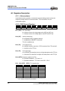
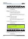
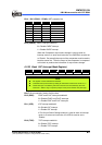
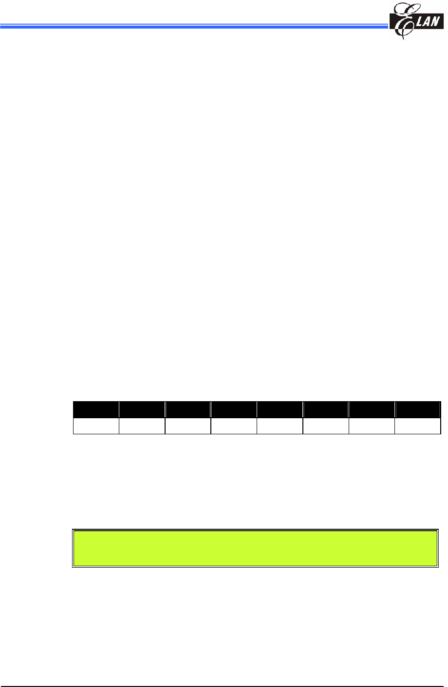
6.2.6 R3 (Status Register)
Bit 7 Bit 6 Bit 5 Bit 4 Bit 3 Bit 2 Bit 1 Bit 0
- - - T P Z DC C
Bits 7~5: not used, fixed to 0 all the time.
Bit 4 (T): Time-out bit. Set to 1 by the "SLEP" and "WDTC" commands or during
power on and reset to 0 by WDT time-out.
Bit 3 (P): Power-down bit. Set to 1 during power on or by a "WDTC" command
and reset to 0 by a "SLEP" command.
NOTE
Bit 4 & Bit 3 (T & P) are read only.
Bit 2 (Z): Zero flag. Set to "1" if the result of an arithmetic or logic operation is
zero.
Bit 1 (DC): Auxiliary carry flag
Bit 0 (C): Carry flag