


EM78P221/2N
8-Bit Microcontroller with OTP ROM
Product Specification (V1.0) 10.19.2007 • 17
(This specification is subject to change without further notice)
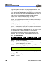
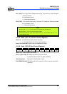
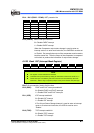
Bit 4 ~ Bit 2 (PSW2 ~ PSW0): WDT prescaler bits
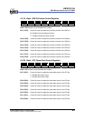
PSW2 PSW1 PSW0 WDT Rate
0 0 0 1:2
0 0 1 1:4
0 1 0 1:8
0 1 1 1:16
1 0 0 1:32
1 0 1 1:64
1 1 0 1:128
1 1 1 1:256
Bit 0 (CMPIE): CMPIF interrupt enable bit
0 = Disable CMPIF interrupt
1 = Enable CMPIF interrupt
When the Comparator output status change is used to enter an
interrupt vector or to enter next instruction, the CMPIE bit must be set
to “Enable“. But actually the output of the comparator must be read to
latch the status first. Then the output of the comparator is compared
to this latch to produce the information of output status change.
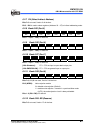
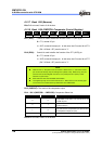
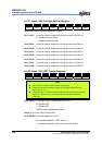
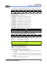
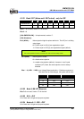
6.2.23 Bank 1-RF (Interrupt Mask Register)
Bit 7 Bit 6 Bit 5 Bit 4 Bit 3 Bit 2 Bit 1 Bit 0
0 0 0 0 0 EXIE ICIE TCIE
NOTE
RF register is both readable and writable.
Individual interrupt is enabled by setting its associated control bit in the RF to "1."
Global interrupt is enabled by the ENI instruction and is disabled by the DISI
instruction. Refer to Fig. 6-8 (Interrupt Input Circuit) under Section 6.6 (Interrupt).
Bits 7~3: not used bits, fixed to 0 all the time
Bit 2 (EXIE): EX0IF and EX1IF interrupts enable bit
0 = Disable EX0IF and EX1IF interrupts
1 = Enable EX0IF and EX1IF interrupts
Bit 1 (ICIE): ICIF interrupt enable bit
0 = Disable ICIF interrupt
1 = Enable ICIF interrupt
If Port 6 Input Status Change Interrupt is used to enter an interrupt
vector or to enter next instruction, the ICIE bit must be set to
“Enable“.
Bit 0 (TCIE): TCIF interrupt enable bit
0 = Disable TCIF interrupt
1 = Enable TCIF interrupt