


EM78P221/2N
8-Bit Microcontroller with OTP ROM
Product Specification (V1.0) 10.19.2007 • 41
(This specification is subject to change without further notice)
6.8 Oscillator
6.8.1 Oscillator Modes
The EM78P221/2N can be operated in six different oscillator modes, such as High
Crystal oscillator mode (HXT 1, 2), Low Crystal oscillator mode (LXT 1, 2), External RC
oscillator mode (ERC), and RC oscillator mode with Internal RC oscillator (IRC). Select
one of such modes by programming the OSC2, OCS1, and OSC0 in the Code Option
register.
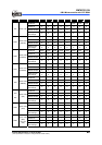
The Oscillator modes defined by OSC2, OCS1, and OSC0 are described below.
Oscillator Modes OSC2 OSC1 OSC0
ERC
1
(External RC oscillator mode); P52/OSCO act as P52 0 0 0
ERC
1
(External RC oscillator mode); P52/OSCO act as OSCO 0 0 1
IRC
2
(Internal RC oscillator mode); P52/OSCO act as P52 0 1 0
IRC
2
(Internal RC oscillator mode); P52/OSCO act as OSCO 0 1 1
LXT1
3
(Frequency range of XT mode is 1MHz~100kHz) 1 0 0
HXT1
3
(Frequency range of XT mode is 16MHz~6MHz) 1 0 1
LXT2
3
(Frequency range of XT mode is 32kHz) 1 1 0
HXT2
3
(Frequency range of XT mode is 6MHz~1MHz) (Default) 1 1 1
1
In ERC mode, OSCI is used as oscillator pin. OSCO/P52 is defined by code option Word 0 Bit 6 ~ Bit 4.
2
In IRC mode, P53 is normal I/O pin. OSCO/P52 is defined by code option Word 0 Bit 6 ~ Bit 4.
3
In LXT1, LXT2, HXT1 and HXT2 modes; OSCI and OSCO are used as oscillator pins. These pins cannot
and should not be defined as normal I/O pins.
The maximum operating frequency limit of the crystal/resonator at different VDDs, are
as follows:
Conditions VDD Max. Freq. (MHz)
2.1 4
3.0 8
Two clocks
4.5 16
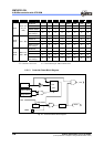
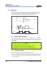
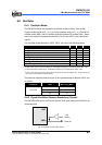
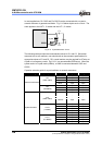
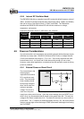
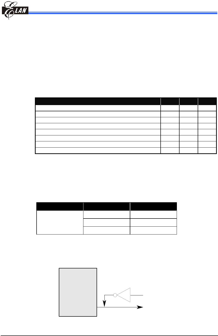
6.8.2 Crystal Oscillator/Ceramic Resonators (Crystal)
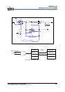
The EM78P221/2N can be driven by an external clock signal through the OSCO pin as
illustrated below.
OSCI
OSCO
Ext.
Clock in
Clock out
Fig. 6-12 External Clock Input Circuit