


EM78P468N/EM78P468L
8-Bit Microcontroller
Product Specification (V1.5) 02.15.2007
• 5
(This specification is subject to change without further notice)
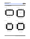
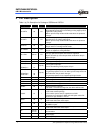
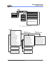
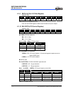
Table 2 (b) Pin Description for Package of QFP44 and LQFP44
Symbol Pin No. Type Function
P5.4/INT0 21 I/O
1-bit General purpose input/output pin/external interrupt.
The INT0 interrupt source can be set to falling or rising edge by
IOC71 register Bit 7 (INT_EDGE).
Wakes up from sleep mode and idle mode when the pin status
changes.
P5.5/INT1 22 I/O
1-bit General purpose input/output pin/external interrupt.
The Interrupt source is a falling edge signal.
Wakes up from sleep mode and idle mode when the pin status
changes.
P5.6/TCC 23 I/O
1-bit General purpose input/output pin/external counter input.
This pin works in normal/green/idle mode.
P5.7/IROUT 24 I/O
1-bit General purpose input/output pin/IR/PWM mode output pin
This pin is capable of sinking 20mA/5V.
P6.0~P6.7 25~32 I/O
8-bit General purpose input/output pins
Pull-high, pull-low and open drain function supported.
All pins can wake up from sleep and idle modes when the pin
status changes.
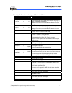
COM3~0 6~9 O
LCD common output pin.
SEG11~SEG14 5~2 O
LCD segment output pin.
SEG16/P7.0
SEG17/P7.1
~
SEG23/P7.7
1
44
~
38
O/(I/O)
LCD segment output pin.
Can be shared with general purpose I/O pin
SEG24/P8.0
~
SEG31/P8.4
37
~
33
O/(I/O)
LCD segment output pin. Can be shared with general I/O pin
For general purpose I/O use, can wake up from sleep mode and
idle mode when the pin status changes.
For general purposes I/O use, supports pull-high function.
VB 10 O
Connect capacitors for LCD bias voltage.
VA 11 O
Connect capacitors for LCD bias voltage.
VLCD2 12 O
One of LCD bias voltage.
VLCD3 13 O
One of LCD bias voltage.
/RESET 14 I
General-purpose Input only
Low active. If it remains at logic low, the device will be reset.
R-OSCI 16 I
In Crystal mode: crystal input
In RC mode: resistor pull high.
In PLL mode: connect 0.01μF capacitance to GND
Connect 0.01μF capacitor to GND and code option select PLL
mode when high oscillator is not use
OSCO 17 O
In Crystal mode: crystal input
In RC mode: instruction clock output
Xin 19 I
In Crystal mode: Input pin for sub-oscillator. Connect to a
32.768kHz crystal.
Xout 20 o
In Crystal mode: Connect to a 32.768kHz crystal.
In RC mode: instruction clock output
VDD 18 I
Power supply
GND 15 I
System ground pin