


EM78P468N/EM78P468L
8-Bit Microcontroller
Product Specification (V1.5) 02.15.2007
• 29
(This specification is subject to change without further notice)
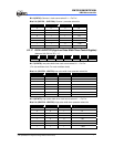
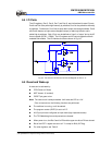
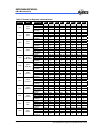
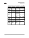
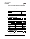
The controller can be awakened from sleep mode and idle mode. The wake-up signals
are listed as follows:
Wake-up Signal Sleep Mode Idle Mode Green Mode Normal Mode
TCC time out
IOCF0 Bit 0=1
× ×
Interrupt Interrupt
INT0 pin
IOCF0 Bit 1=1
Wake-up
+ interrupt
+ next instruction
Wake-up
+ interrupt
+ next instruction
Interrupt Interrupt
INT1 pin
IOCF0 Bit 2=1
Wake-up
+ interrupt
+ next instruction
Wake-up
+ interrupt
+ next instruction
Interrupt Interrupt
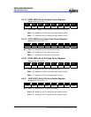
Counter 1
IOCF0 Bit 3=1
×
Wake-up
+ interrupt
+ next instruction
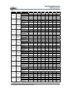
Interrupt Interrupt
Counter 2
IOCF0 Bit 4=1
×
Wake-up
+ interrupt
+ next instruction
Interrupt Interrupt
High-pulse timer
IOCF0 Bit 5=1
×
Wake-up
+ interrupt
+ next instruction
Interrupt Interrupt
Low-pulse timer
IOCF0 Bit 6=1
×
Wake-up
+ interrupt
+ next instruction
Interrupt Interrupt
Port 6, Port 8
(input status
change wake-up)
Bit 7 of IOCF0 = “0”
Wake-up
+ next instruction
Wake-up
+ next instruction
× ×
Port 6, Port 8
(input status
change wake-up)
Bit 7 of IOCF0 = “1”
Wake-up
+ interrupt
+ next instruction
Wake-up
+ interrupt
+ next instruction
× ×
WDT time out
×
RESET RESET RESET