


EM78P468N/EM78P468L
8-Bit Microcontroller
Product Specification (V1.5) 02.15.2007
• 19
(This specification is subject to change without further notice)
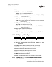
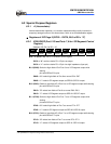
Bit 2 (/WUE8L): 0/1 → enable/disable P8.0~P8.3 pin change wake-up function
Bit 1 (/WUE6H): 0/1 → enable/disable P6.4~P6.7 pin change wake-up function
Bit 0 (/WUE6L): 0/1 → enable/disable P6.0~P6.3 pin change wake-up function
* Port 6 and Port 8 must not be set as input floating when wake-up function is
enabled. “Enable” is the initial state of wake-up function.
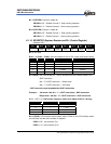
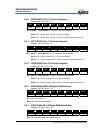
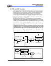
6.2.14 IOC71/TCCCR (TCC Control Register)
(Address: 07h, Bit 0 of R5 = “1”)
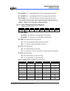
Bit 7 Bit 6 Bit 5 Bit 4 Bit 3 Bit 2 Bit 1 Bit 0
INT_EDGE INT TS TE PSRE TCCP2 TCCP1 TCCP0
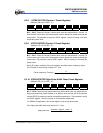
Bit 7 (INT_EDGE):
INT_EDGE = “0”:
Interrupt on the rising edge of P5.4/INT0 pin
INT_EDGE = “1”: Interrupt on the falling edge of P5.4/INT0 pin
Bit 6 (INT): INT enable flag, this bit is read only
INT = “0”: interrupt masked by DISI or hardware interrupt
INT = “1”: interrupt enabled by ENI/RETI instructions
Bit 5 (TS): TCC signal source
TS = “0”: internal instruction cycle clock
TS = “1”: transition on TCC pin, TCC period > internal instruction clock period
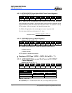
Bit 4 (TE):
TCC signal edge
TE = “0”: incremented by TCC pin rising edge
TE = “1”: incremented by TCC pin falling edge
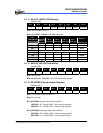
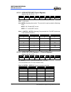
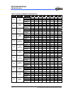
Bits 3~0 (PSRE, TCCP2 ~ TCCP0): TCC prescaler bits.
PSRE TCCP2 TCCP1 TCCP0 TCC Rate
0 × × × 1:1
1 0 0 0 1:2
1 0 0 1 1:4
1 0 1 0 1:8
1 0 1 1 1:16
1 1 0 0 1:32
1 1 0 1 1:64
1 1 1 0 1:128
1 1 1 1 1:256