


EM78P468N/EM78P468L
8-Bit Microcontroller
Product Specification (V1.5) 02.15.2007
• 45
(This specification is subject to change without further notice)
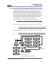
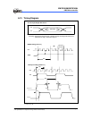
6.11 Code Options
The EM78P468N/L has one Code Option word that is not a part of the normal program
memory. The option bits cannot be accessed during normal program execution.
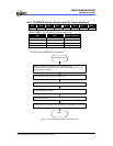
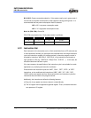
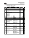
Code Option Register and Customer ID Register arrangement distribution:
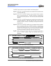
Word 1 of code options is for customer ID code application.
Word 1
Bit 12~Bit 0
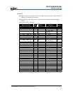
Word 0 of Code Options is for IC function setting. The following are the settings for
OTP IC programming
:
Word 0
Bits12~10 Bit 9 Bit 8 Bit 7 Bit 6 Bit 5 Bit 4 Bit 3 Bit 2 Bit 1 Bit 0
1 CYES HLFS ENWDTB FSMD FMMD1 FMMD0 HLP PR2 PR1 PR0
Bits 12 ~ 10: Not used.
These bits are set to “1” all the time.
Bit 9 (CYES): Cycle select for JMP and CALL instructions
CYES = “0”: only one instruction cycle (JMP or CALL) can be executed
CYES = “1”: two instructions cycles (JMP and CALL) can be executed
Bit 8 (HLFS): main or sub-oscillator select
HLFS = “0”: CPU is set to select sub-oscillator when reset occurs.
HLFS = “1”: CPU is set to select main-oscillator when reset occurs.
Bit 7 (ENWDTB): Watchdog timer enable/disable bit.
ENWDTB = “0”: Enable watchdog timer.
ENWDTB = “1”: Disable watchdog timer.
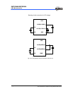
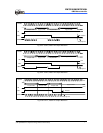
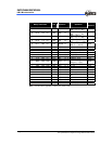
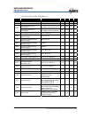
Bit 6 (FSMD): sub-oscillator type selection.
Bits 5, 4 (FMMD1, 0): Main Oscillator Type Selection
FSMD FMMD1 FMMD0 Main Oscillator Type Sub Oscillator Type
0 0 0 RC type RC type
0 0 1 Crystal type RC type
0
1
×
PLL type RC type
1 0 0 RC type Crystal type
1 0 1 Crystal type Crystal type
1
1
×
PLL type Crystal type