


EM78P468N/EM78P468L
8-Bit Microcontroller
Product Specification (V1.5) 02.15.2007
• 13
(This specification is subject to change without further notice)
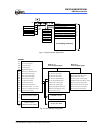
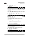
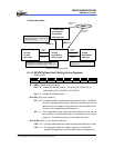
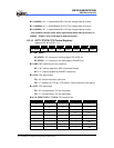
CPU Operation Mode
Green Mode
fm:stop
fs: oscillation
CPU: using fs
Normal Mode
fm:oscillation
fs: oscillation
CPU: using fosc
IDLE Mode
fm:stop
fs: oscillation
CPU: stop
SLEEP Mode
Fm:stop
Fs: stop
CPU: stop
IDLE="1"
SLEP
IDLE="0"
SLEP
wake upWake up
RESET
CPUS="1"
CPUS="0"
Code option
HLFS=0
Code option
HLFS=1
The wake up time from idle to green
mode is 16*1/fs
The w ake up time from sleep to green mode is
approximately sub-oscillator setup time +18ms+16*1/fs
it must delay a little times f or the main
oscillation stable while your system timing
control is conscientious
Fig. 6-3 CPU Operation Mode
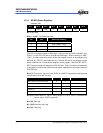
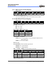
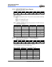
6.1.15 RE/IRCR (IR and Port 5 Setting Control Register)
(Address: 0Eh)
Bit 7 Bit 6 Bit 5 Bit 4 Bit 3 Bit 2 Bit 1 Bit 0
IRE HF LGP − IROUTE TCCE EINT1 EINT0
Bit 7 (IRE): Infrared Remote Enable bit
IRE = “0” : Disable the IR/PWM function. The state of P5.7/IROUT pin is
determined by Bit 7 of IOC 50 if it is for IROUT.
IRE = “1” : Enable IR or PWM function.
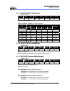
Bit 6 (HF): High carry frequency
HF = “0” : For PWM application, disable the H/W modulator function. The IROUT
waveform is generated according to high-pulse and low-pulse time as
determined by the respective high pulse and low pulse width timers.
Counter 2 is an independent auto reload timer.
HF = “1” : For IR application mode, enable the H/W modulator function, the low
time sections of the generated pulse is modulated with the Fcarrier
frequency. The Fcarrier frequency is provided by Counter 2.
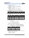
Bit 5 (LGP): IROUT for of low pulse width timer
LGP = “0” : The high-pulse width timer register and low-pulse width timer is valid.
LGP = “1” : The high-pulse width timer register is ignored. So the IROUT
waveform is dependent on the low-pulse width timer register only.