


EM78P468N/EM78P468L
8-Bit Microcontroller
Product Specification (V1.5) 02.15.2007
• 31
(This specification is subject to change without further notice)
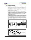
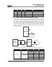
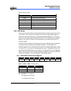
Bits 6~4 (CLK2~0) of RD: main clock selection bits for PLL mode (code option select)
CLK2 CLK1 CLK0 Main clock Example Fs=32.768KHz
0 0 0 Fs×130 4.26 MHz
0 0 1 Fs×65 2.13 MHz
0 1 0 Fs×65/2 1.065 MHz
0 1 1 Fs×65/4 532 kHz
1 × × Fs×244 8 MHz
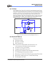
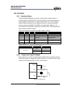
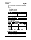
6.6.3 Crystal Oscillator/Ceramic Resonators (Crystal)
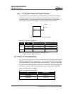
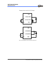
This LSI can be driven by an external clock signal through the R-OSCI pin as shown in
Fig.6-7 below. In most applications, the R-OSCI pin and the OSCO pin can be
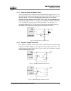
connected with a crystal or ceramic resonator to generate oscillation. Fig. 6-8 depicts
such circuit. Table 5 provides the recommended values of C1 and C2. Since each
resonator has its own attribute, user should refer to its specification for appropriate
values of C1 and C2. RS, a serial resistor, may be necessary for AT strip cut crystal or
low frequency mode.
EM78P468N
OSCO
R-OSCI
Fig. 6-7 External Clock Input Circuit
EM78P468N
OSCO
R-OSCI
XT AL
Rs
C1
C2
EM78P468N
Xout
Xin
XT AL
Rs C2
C1
Fig. 6-8 Circuit for Crystal/Resonator
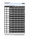
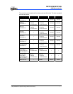
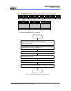
Table 5 Capacitor Selection Guide for Crystal Oscillator or Ceramic Resonators
Oscillator Source Oscillator Type Frequency C1 (pF) C2 (pF)
455 kHz 100~150 100~150
2.0 MHz 20~40 20~40
Ceramic Resonators
4.0MHz 10~30 10~30
455kHz 20~40 20~150
1.0MHz 15~30 15~30
2.0MHz 15 15
Main oscillator
Crystal Oscillator
4.0MHz 15 15
Sub-oscillator Crystal Oscillator 32.768kHz 25 25