


EM78P468N/EM78P468L
8-Bit Microcontroller
42 •
Product Specification (V1.5) 02.15.2007
(This specification is subject to change without further notice)
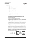
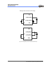
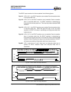
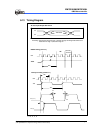
The IROUT output waveform is further explained in the following figures:
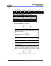
Fig. 6-21 LGP=0, HF=1, the IROUT waveform can modulate Fcarrier waveform when
in low-pulse width time.
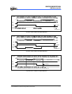
Fig. 6-22 LGP=0, HF=0, the IROUT waveform cannot modulate Fcarrier waveform
when in low-pulse width time. So IROUT waveform is determined by
high-pulse time and low-pulse time. This mode can produce standard PWM
waveform.
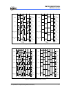
Fig. 6-23 LGP=0, HF=1, the IROUT waveform can modulate Fcarrier waveform when
in low-pulse width time. When IRE goes from high to low, the output
waveform of IROUT will keep on transmitting until high-pulse width timer
interrupt occurs.
Fig. 6-24 LGP=0, HF=0, the IROUT waveform can not modulate Fcarrier waveform
when in low-pulse width time. So IROUT waveform is determined by
high-pulse time and low-pulse time. This mode can produce standard PWM
waveform. When IRE goes from high to low, the output waveform of IROUT
will keep on transmitting till high-pulse width timer interrupt occurs.
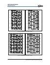
Fig.6-25 LGP=1, when this bit is set to high level, the high-pulse width timer is
ignored. So IROUT waveform output from low-pulse width timer is
established.
Fcarrier
low-pulse width high-pulse width
IROUT
start
HF
IRE
high-pulse width
low-pulse width
Fig. 6-21 LGP=0, IROUT Pin Output Waveform
Fcarrier
low-pulse width high-pulse width
IROUT
start
HF
IRE
high-pulse width
low-pulse width
Fig. 6-22 LGP=0, IROUT Pin Output Waveform