


EM78P468N/EM78P468L
8-Bit Microcontroller
Product Specification (V1.5) 02.15.2007
• 41
(This specification is subject to change without further notice)
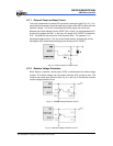
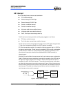
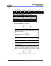
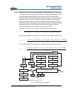
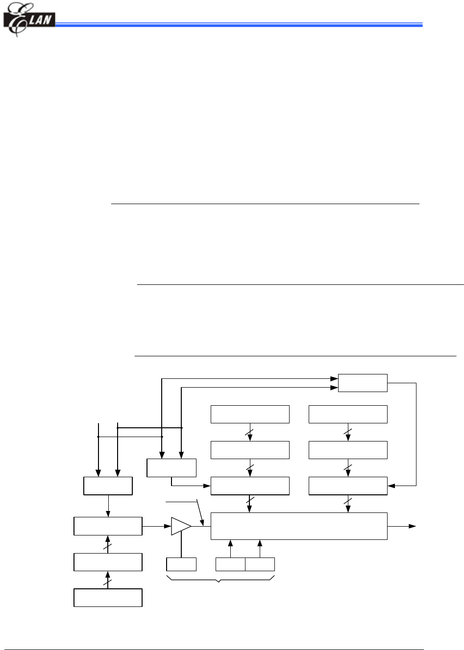
6.10 Infrared Remote Control Application/PWM Waveform Generate
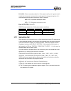
This LSI can output infrared carrier in user-friendly or in PWM standard waveform. The IR
and PWM waveform generated functions include an 8-bit down count timer/counter,
high-pulse width timer, low-pulse width timer, and IR control register. The IR system block
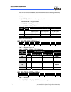
diagram is shown in Fig. 6-20. The IROUT pin waveform is determined by IR control
register (RE), IOC90 (Counters 1 and 2 control register), IOCA0 (high-pulse width timer,
low-pulse width timer control register), IOCC0 (Counter 2 preset), IOCD0 (high-pulse width
timer preset register), and IOCE0 (low-pulse width timer preset register). Details on
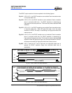
Fcarrier, high-pulse time, and low pulse time are explained as follows
:
If Counter 2 clock source is F
T
(this clock source can be set by IOC91), then
prescalerIOCCvaluepresetounterofdecimal
F
F
T
carrier
×+×
=
))0(2C1(2
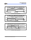
If the high-pulse width timer clock source is FT (this clock source can be set by IOCA1), then
T
timepulsehigh
F
IOCDvaluetimerwidthpulsehighofdecimalprescaler
T
))0(1( +×
=
If the low-pulse width timer clock source is FT (this clock source can be set by IOCA1);
T
timepulselow
F
IOCEvaluetimerwidthpulselowofdecimalprescaler
T
))0(1( +×
=
H/W Modulator Circuit
Pre-scaler
(IOC91)
8 bit down counter
Fs
8 bit dow n counter
Pre-scaler
(IOC A1)
8
Auto-reload buffer
Auto-reload buffer
8
8
8 bit dow n counter
8
Auto-reload buffer
8
IROUT pin
Pre-scaler
(IOCA1)
IRE
Fcarrier
Fm
LGP
High-Pulse Width Timer
(IOCD0)
Low -Pulse Width Timer
( IOCE0)
HF
Counter 2
(IOCC0)
8
RE register
88
Fm: main oscillator frequency Fs: sub-oscillator frequency
Fig. 6-20 IR/PWM System Block Diagram