Setting Up the System 2-11
Rear View
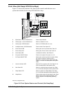
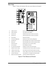
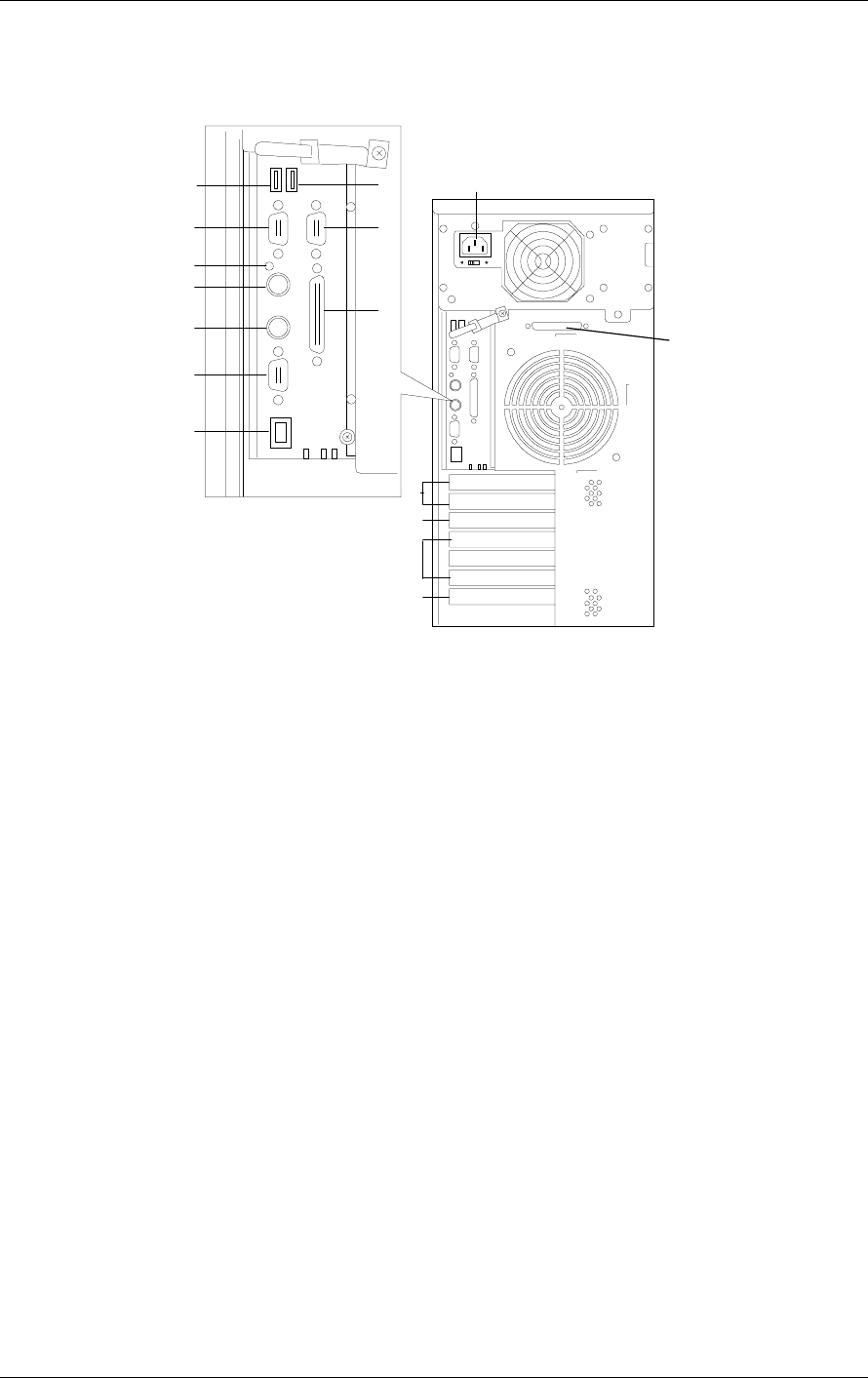
Figure 2-7 shows the location of the rear system features and controls.
A
B
C
D
E
F
G
H
I
J
K
L
M
N
O
P
A. USB2 connector Second USB connector (Black)
B. USB1 connector First USB connector (Black)
C. Serial Port B COM2 serial port 9-pin connector (Turquoise)
D. Serial Port A COM1 serial port 9-pin connector (Turquoise)
E. Dump button Reserved for debug
F. Printer port (Burgundy) Parallel port 25-pin connector (Burgundy)
G. Keyboard port PS/2-compatible 6-pin mini-DIN connector (Purple)
H. Mouse port PS/2-compatible 6-pin mini-DIN connector (Green)
I. SVGA connector SVGA monitor 15-pin connector (Blue)
J. LAN connector RJ-45 Ethernet connector
K. AC input power connector Supplies AC power to the power supply.
L. 66 MHz, 64-bit PCI Slots Two 66 MHz, 64-bit PCI add-in board slot locations
M. 33 MHz, 64-bit PCI Slot One 33 MHz, 64-bit PCI add-in board slot location
N. 33 MHz, 32-bit PCI Slots Three 33 MHz, 32-bit PCI add-in board slot locations
O.
Combo PCI/ISA slot One shared PCI or ISA add-in board slot location
P.
Wide Ultra 2 SCSI Connector Connects to External SCSI Devices
Figure 2-7. Rear Features and Controls


