


Intel
®
6321ESB ICH—Thermal Metrology
Intel
®
631xESB/632xESB I/O Controller Hub for Embedded Applications
TMDG February 2007
16
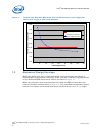
6.0 Thermal Metrology
The system designer must make temperature measurements to accurately determine
the thermal performance of the system. Intel has established guidelines for proper
techniques to measure the Intel® 6321ESB I/O Controller Hub die temperatures.
Section 6.1 provides guidelines on how to accurately measure the Intel
®
6321ESB ICH
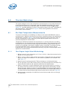
die temperatures. The flowchart in Figure 6 offers useful guidelines for thermal
performance and evaluation.
6.1 Die Case Temperature Measurements
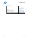
To ensure functionality and reliability, the Tcase of the Intel
®
6321ESB ICH must be
maintained at or between the maximum/minimum operating range of the temperature
specification as noted in Table 3. The surface temperature at the geometric center of
the die corresponds to Tcase. Measuring Tcase requires special care to ensure an
accurate temperature measurement.
Temperature differences between the temperature of a surface and the surrounding
local ambient air can introduce errors in the measurements. The measurement errors
could be due to a poor thermal contact between the thermocouple junction and the
surface of the package, heat loss by radiation and/or convection, conduction through
thermocouple leads, and/or contact between the thermocouple cement and the
heatsink base. For maximize measurement accuracy, only the 0° thermocouple attach
approach is recommended.
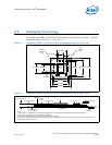
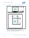
6.1.1 Zero Degree Angle Attach Methodology
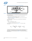
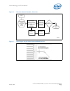
1. Mill a 3.3 mm (0.13 in.) diameter and 1.5 mm (0.06 in.) deep hole centered on the
bottom of the heatsink base.
2. Mill a 1.3 mm (0.05 in.) wide and 0.5 mm (0.02 in.) deep slot from the centered
hole to one edge of the heatsink. The slot should be parallel to the heatsink fins
(see Figure 7).
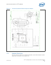
3. Attach thermal interface material (TIM) to the bottom of the heatsink base.
4. Cut out portions of the TIM to make room for the thermocouple wire and bead. The
cutouts should match the slot and hole milled into the heatsink base.
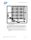
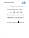
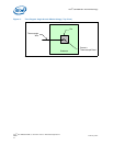
5. Attach a 36 gauge or smaller calibrated K-type thermocouple bead or junction to
the center of the top surface of the die using a high thermal conductivity cement.
During this step, ensure no contact is present between the thermocouple cement
and the heatsink base because any contact will affect the thermocouple reading. It
is critical that the thermocouple bead makes contact with the die (see Figure 8).
6. Attach heatsink assembly to the MCH and route thermocouple wires out through
the milled slot.