82540EP — Networking Silicon
12 Datasheet
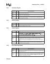
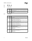
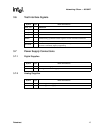
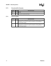
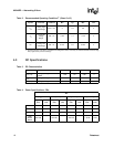
3.2.6 Power Management Signals
3.2.7 Impedance Compensation Signals
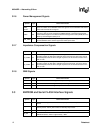
3.2.8 SMB Signals
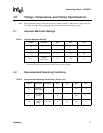
3.3 EEPROM and Serial FLASH Interface Signals
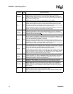
Symbol Type Name and Function
LAN_
PWR_
GOOD
I
Power Good (Power-on Reset). The Power Good signal is used to indicate that stable
power is available for the 82540EP. When the signal is low, the 82540EP holds itself in
reset state and floats all PCI signals.
PME# OD
Power Management Event. The 82540EP device drives this signal low when it
receives a wake-up event and either the PME Enable bit in the Power Management
Control/Status Register or the Advanced Power Management Enable (APME) bit of the
Wake-up Control Register (WUC) is 1b.
AUX_PWR I
Auxiliary Power. If the Auxiliary Power signal is high, then auxiliary power is available
and the 82540EP device should support the D3cold power state.
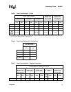
Symbol Type Name and Function
ZN_COMP I/O
N Device Impedance Compensation. This signal should be connected to an external
precision resistor (to VDD) that is indicative of the PCI trace load. This cell is used to
dynamically determine the drive strength required on the N-channel transistors in the
PCI I/O cells.
ZP_COMP I/O
P Device Impedance Compensation. This signal should be connected to an external
precision resistor (to VSS) that is indicative of the PCI trace load. This cell is used to
dynamically determine the drive strength required on the P-channel transistors in the
PCI I/O cells.
Symbol Type Name and Function
SMBCLK I/O SMB Clock. The SMB Clock signal is an open drain signal for serial SMB interface.
SMBDATA I/O
SMB Data. The SMB Data signal is an open drain signal for serial SMB interface.
SMBALRT# O
SMB Alert. The SMB Alert signal is open drain for serial SMB interface.
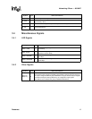
Symbol Type Name and Function
EE_DI O
EEPROM Data Input. The EEPROM Data Input pin is used for output to the memory
device.
EE_DO I
EEPROM Data Output. The EEPROM Data Output pin is used for input from the
memory device. The EE_DO includes an internal pull-up resistor.
EE_CS O
EEPROM Chip Select. The EEPROM Chip Select signal is used to enable the device.
EE_SK O
EEPROM Serial Clock. The EEPROM Shift Clock provides the clock rate for the
EEPROM interface, which is approximately 1 MHz.


