82540EP — Networking Silicon
30 Datasheet
5.4 Pinout Information
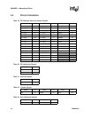
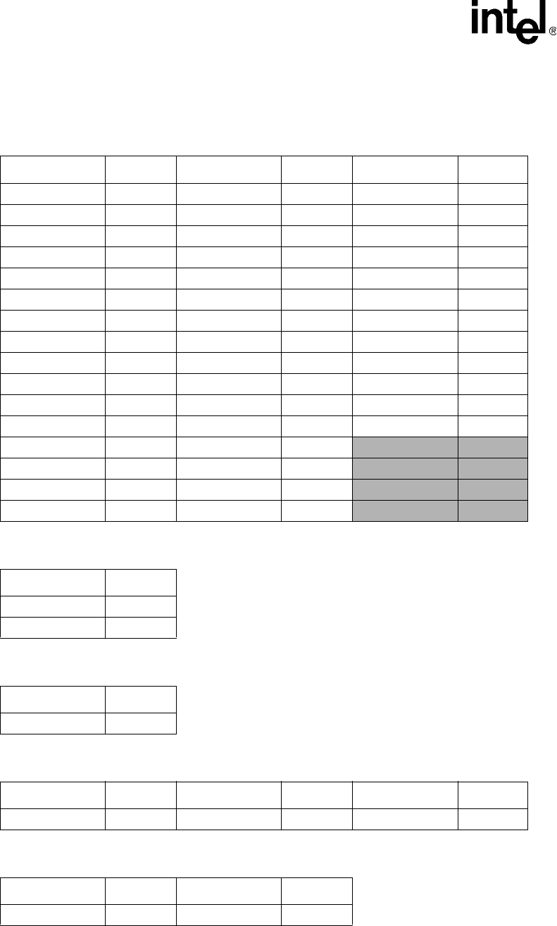
Table 19. PCI Address, Data, and Control Signals
Signal Pin Signal Pin Signal Pin
PCI_AD[0] N7 PCI_AD[16] K1 CBE0# M4
PCI_AD[1] M7 PCI_AD[17] E3 CBE1# L3
PCI_AD[2] P6 PCI_AD[18] D1 CBE2# F3
PCI_AD[3] P5 PCI_AD[19] D2 CBE3# C4
PCI_AD[4] N5 PCI_AD[20] D3 PAR J1
PCI_AD[5] M5 PCI_AD[21] C1 FRAME# F2
PCI_AD[6] P4 PCI_AD[22] B1 IRDY# F1
PCI_AD[7] N4 PCI_AD[23] B2 TRDY# G3
PCI_AD[8] P3 PCI_AD[24] B4 STOP# H1
PCI_AD[9] N3 PCI_AD[25] A5 DEVSEL# H3
PCI_AD[10] N2 PCI_AD[26] B5 VIO G2
PCI_AD[11] M1 PCI_AD[27] B6 IDSEL A4
PCI_AD[12] M2 PCI_AD[28] C6
PCI_AD[13] M3 PCI_AD[29] C7
PCI_AD[14] L1 PCI_AD[30] A8
PCI_AD[15] L2 PCI_AD[31] B8
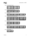
Table 20. PCI Arbitration Signals
Signal Pin
REQ# C3
GNT# J3
Table 21. Interrupt Signals
Signal Pin
INTA# H2
Table 22. System Signals
Signal Pin Signal Pin Signal Pin
CLK G1 M66EN C2 RST# B9
Table 23. Error Reporting Signals
Signal Pin Signal Pin
SERR# A2 PERR# J2


