


Datasheet 9
Networking Silicon — 82555
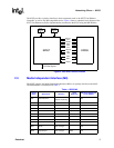
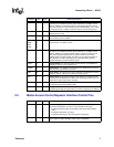
3.5 Media Access Control/Repeater Interface Control Pins
RXC 90 O
Receive Clock.
The Receive Clock may be either 25 MHz or 2.5 MHz
depending on the 82555’s operating speed (25 MHz for 100 Mbps and 2.5
MHz for 10 Mbps). The Receive Clock is recovered directly from incoming
data and is continuous into the Media Access Controller (MAC). Thus, it must
be resynchronized in 10 Mbps mode at the start of each incoming packet.
RXDV 86 O
Receive Data Valid.
This signal indicates that the incoming data on the
RSC[3:0] pins are valid.
RXERR 87 O
Receive Error.
The RXERR signal indicates to the 82555 that an error has
occurred during frame reception.
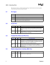
TXD3
TXD2
TXD1
TXD0
71
70
69
68
I
Transmit Data.
In 100 Mbps and 10 Mbps mode, data is transferred across
these four lines one nibble at a time.
TXC 60 I/O
Transmit Clock.
The Transmit Clock may be either 25 MHz or 2.5 MHz
depending on the 82555’s operating speed (25 MHz for 100 Mbps and 2.5
MHz for 10 Mbps). The Transmit Clock outputs a continuous clock into the
MAC that is generated directly from the external clock source in DTE
(adapter) mode. In repeater mode, the TXC is an input signal operating at
either 25 MHz or 2.5 MHz depending on the operating speed, which is
typically clocked by a receiver interface device.
TXEN 79 I
Transmit Enable.
The Transmit Enable signal indicates to the 82555 that
valid data is present on the TXD[3:0] pins.
TXERR 59 I
Transmit Error.
The TXERR signal indicates to the 82555 that an error has
occurred during transmissions of a frame.
CRS 82 O
Carrier Sense.
The Carrier Sense signal indicates to the 82555 that traffic is
present on the link. CRS is an asynchronous output signal.
COL 85 O
Collision Detect.
The Collision Detect signal operates in half duplex mode
and indicates to the 82555 that a collision has occurred on the link. COL is an
asynchronous output signal to the controller.
MDIO 80 I/O
Management Data Input/Output.
The MDIO signal is a bidirectional data pin
for the Management Data Interface (MDI).
MDC 81 II
Management Data Clock.
The MDC signal functions as a clock reference for
the MDIO signal. MDC should operate at a maximum frequency of 2.5 MHz
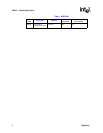
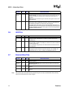
Symbol Pin Type Name and Function
RXCONG 77 I
Receive Congestion.
If the following conditions exist, the RXCONG is an
active high and indicates an overrun on the controller receive side:
• Full duplex PHY Base (Bay Technologies) flow control DTE (adapter)
mode
• Full duplex signal (FDX_N) is high
• Full duplex technology is active through Auto-Negotiation
PORTEN 76 I
Port Enable.
In repeater mode when the PORTEN signal is low, the following
signals will be tri-stated: RXD[3:0], RXC, RXDV, and RXERR.
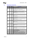
Symbol Pin Type Name and Function