


82555 — Networking Silicon
28
Datasheet
The 82555 address can be configured to four 0 through 3 in DTE (adapter) mode and 0 through 31
in repeater mode. A special functions for switches allows 32 addresses to exist in repeater mode.
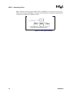
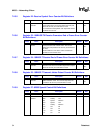
The management frame structure is as follows:
7.2 MDI Registers
MDI registers are described in the following subsections and the acronyms mentioned in the
registers are defined as follows:
SC - Self Cleared.
RO -Read Only.
P- External pin affects 82555 register content.
LL - Latch Low.
LH - Latch High.
7.2.1 MDI Registers 0 - 7
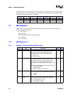
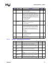
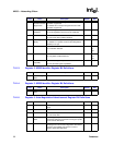
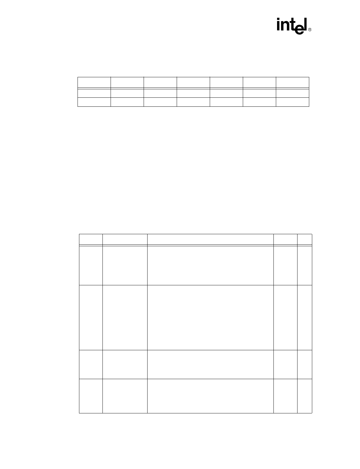
7.2.1.1 Register 0: Control Register Bit Definitions
Transition ST OP PHYAD REGAD TA DATA
READ <01> <10> <AAAAA> <RRRRR> <
X
0> 16 bits
WRITE <01> <01> <AAAAA> <RRRRR> <10> 16 bits
Bit(s) Name Description Default R/W
15 Reset This bit sets the status and control register of the 82555
to their default states and is self-clearing. The PHY
returns a value of 1b until the reset process has
completed and accepts a read or write transaction.
1 = PHY Reset
0 = Normal operation
0RW
SC
14 Loopback This bit enables loopback of transmit data nibbles from
the TXD[3:0] signals to the receive data path. The
82555’s receive circuitry is isolated from the network.
Note that this may cause the descrambler to lose
synchronization and produce 560 nanoseconds of “dead
time.”
Note also that the loopback configuration bit takes priority
over the Loopback MDI bit.
1 = Loopback enabled
0 = Loopback disabled (normal operation)
0RW
P
13 Speed Selection This bit controls speed when Auto-Negotiation is disabled
and is valid on read when Auto-Negotiation is disabled.
1 = 100 Mbps
0 = 10 Mbps
1RW
P
12 Auto-Negotiation
Enable
This bit enables Auto-Negotiation. Bits 13 and 8, Speed
Selection and Duplex Mode, respectively, are ignored
when Auto-Negotiation is enabled.
1 = Auto-Negotiation enabled
0 = Auto-Negotiation disabled
1RW