Datasheet 41
Networking Silicon — 82555
10.0 Reset and Miscellaneous Test Modes
10.1 Reset
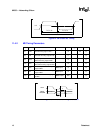
When the 82555 RESET signal is asserted (high), all internal circuits are reset. TXC and RXC
should run continuously even though RESET is active. The 82555 may also be reset through the
MDI reset bit.
10.2 Loopback
When the loopback pin is being driven high, the 82555 executes a loopback diagnostics operation.
This mode can also be accessed through the MDI registers.
10.3 Scrambler Bypass
When the Scrambler Bypass pin is active, the 82555 bypasses the scrambler/descrambler. This
mode can also be accessed through the MDI registers.
10.4 Test Port
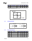
When the TESTEN pin is high, the test pins provide a test access port for the 82555. In test mode,
the 82555 will default to address 1. The 82555 has a simple Test Access Port (TAP) from which all
the test modes are selected and test instructions are operated. The TAP is controlled by a simple
mechanism and handshake. Activation of all test modes requires simple hardware. The TAP signals
connected to the 82555 blocks and periphery control the 82555’s mode of operation to allow simple
testing and internal built-in self testing.
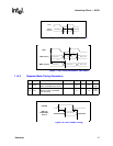
The test instruction are shifted into the Test Instruction Shift Register (TISR) through the TIN pin.
The TIN pin is sampled on the rising edge of the TCK input signal. The instruction is transferred
from the TISR to the Test Instruction Register (TIR) when TESTEN is sampled high on the rising
edge of TCK. As a general rule, all the TAP input and output pins are activated by the rising edge of
TCK. If TCK is a constant clock signal, then TESTEN must be 1 clock pulse width.
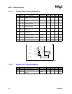
When the TIR receives a new instruction, the instruction is decoded into control signals and
synchronized to the 10 MHz clock. These control signals set the 82555 blocks into various test
modes. In order to achieve stable synchronization between the clock signal (X1) and the TCK
signal, the TCK input signal frequency should be less than or equal to half of the clock input signal
frequency.


