


Datasheet 27
Networking Silicon — 82555
7.0 Management Data Interface
The 82555 provides status and accepts management information through the Management Data
Interface (MDI). This is accomplished through read and write operations to various registers in
accordance with the IEEE 802.3u MII specification.
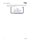
7.1 MDI Frame Structure
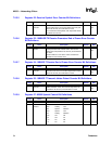
Data read from or written to a particular register is called a management frame and is sent serially
over the MDIO pin synchronously to the MDC signal. Read and write cycles are viewed from the
perspective of the controller. Thus, the controller always drives the start, opcode, PHY address, and
register address onto the MDIO pin. For read cycles, the controller drives the transition bits and
data onto the MDIO pin; for write cycles, to the 82555. The controller drives addresses and data on
the falling edge of the MDC signal, and the 82555 latches the data on the rising edge of the MDC
signal. The following list defines protocol terms:
PREAMBLE
At the beginning of each transaction, the controller send a sequence of 32
contiguous logic one bits on the MDIO pin with corresponding cycles on the MDC
pin for synchronization by the 82555.
ST
This field contains the value of 01b indicating the start of a frame.
OP
This is a 2-bit field containing one of the following two operation codes: 10b (read)
or 01b (write).
PHYAD
This field is a 5-bit address of the 82555 device that provides support for 32 unique
PHY addresses. The controller drives the value written into the PHYAD portion of
the MDI register in this field.
REGAD
This field is a 5-bit address of a specific register within the 82555. This provides
support for 32 unique registers. The desired register address is specified by the
value written to the MDI register.
TA
This field contains a 2-bit value specifying the period during a read cycle that no
device may actively drive the MDIO signal. During a read transaction, the 82555
should not drive the MDIO signal in the first bit time; however, it will drive a 0b in
the second bit time. During a write transaction, the controller drives the pattern of
10b to fill this time.
DATA
This field contains 16 bits of data driven by the 82555 on a read transaction or by
the controller on a write transactions. This data is either control or status parameters
passed between the controller and the 82555.
IDLE
During the idle state, the MDIO signal is in a high impedance state. The MDIO
driver is disabled, and the 82555 will pull the MDIO signal high to a logic 1.