


82555 — Networking Silicon
10
Datasheet
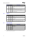
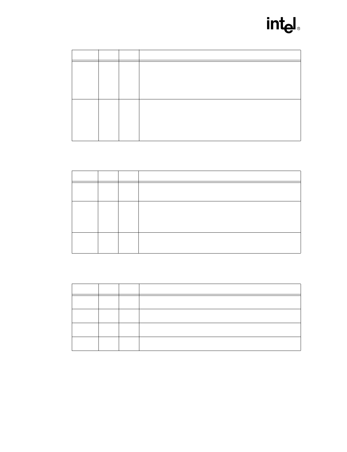
3.6 LED Pins
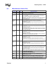
3.7 External Bias Pins
Note: The resistor values described for the external bias pins are only recommended values and may
require to be fine tuned for various designs.
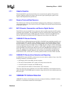
TXRDY
(TOUT)
4 O This pin is multiplexed and can be used for one of the following:
Transmit Ready.
If full duplex and PHY Base (Bay Technologies) flow control
modes are enabled, the TXRDY signal enables transmission while it is
asserted.
TOUT.
When the Test Enable signal is activated, this signal functions as the
Test Output port.
FDX_N 5 I/O
Full Duplex.
In DTE (adapter) mode, this active low output signal reports the
result of the duplex configuration to the MAC. This pin can also operate as
the LED driver and will be an active low for all technologies.
In repeater mode, this signal is used for Auto-Negotiation advertisement to
the 82555’s link partner and activates the PHY Base (Bay Technologies) flow
control if 100BASE-TX full duplex is the highest common technology between
the 82555 and its link partner.
Symbol Pin Type Name and Function
ACTLED 12 O
Activity LED.
This signal indicates either transmit or receive activity. When
activity is present, the ACTLED is on. When no activity is present, the
ACTLED is off.
LILED 11 O
Link Integrity LED.
This signal indicates the link integrity. If a valid link is
present in either 10 Mbps or 100 Mbps, the LILED is on; and if an invalid link
is preset, LILED is off.
For a combination design board, the LILED should be connected to the TX
technology LED.
SPEED-
LED
13 O Speed LED
This signal is used to indicate the speed of operation. For 100 Mbps, the
SPEEDLED will be on; and for 10 Mbps, the SPEEDLED will be off.
Symbol Pin Type Name and Function
RBIAS100 44 B
Bias Reference Resistor 100.
A 634
Ω
resistor should be connected from
this pin to ground.
RBIAS10 43 B
Bias Reference Resistor 10.
A 768
Ω
resistor should be connected from
this pin to ground.
PD1 42 I
Pull Down One.
A 10 K
Ω
resistor should be connected from this pin to
ground.
PD2 100 I
Pull Down One.
A 1 K
Ω
resistor should be connected from this pin to
ground.
Symbol Pin Type Name and Function