


Datasheet 21
Networking Silicon — 82555
5.0 10BASE-T Functionality in Adapter Mode
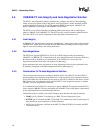
5.1 10BASE-T Transmit Clock Generation
The 20 MHz and 10 MHz clocks needed for 10BASE-T are synthesized from the external 25 MHz
crystal or oscillator. The 82555 provides the transmit clock and receive clock to the MAC at 2.5
MHz.
5.2 10BASE-T Transmit Blocks
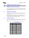
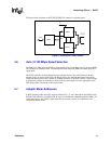
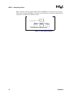
5.2.1 10BASE-T Manchester Encoder
After the 2.5 MHz clocked data is serialized in a 10 Mbps serial stream, the 20 MHz clock
performs the Manchester encoding. The Manchester code always has a mid-bit transition. If the
value is 1b then the transition is from low to high. If the value is 0b then the transition is from high
to low. The boundary transition occurs only when the data changes from bit to bit. For example, if
the value is 10b, then the change is from high to low; if 01b, then the change is from low to high.
5.2.2 10BASE-T Driver and Filter
Since 10BASE-T and 100BASE-TX have different filtration needs, both filters are implemented
inside the chip. This allows the two technologies to share the same magnetics. The 82555 supports
both technologies through one pair of transmit differential pins and by externally sharing the same
magnetics.
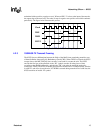
In 10 Mbps mode, the 82555 begins transmitting the serial Manchester bit stream within 3 bit times
(300 nanoseconds) after the MAC asserts TXEN. In 10 Mbps mode the line drivers use a pre-
distortion algorithm to improve jitter tolerance. The line drivers reduce their drive level during the
second half of “wide” (100 ns) Manchester pulses and maintain a full drive level during all narrow
(50 ns) pulses and the first half of the wide pulses. This reduces line overcharging during wide
pulses, a major source of jitter.
5.3 10BASE-T Receive Blocks
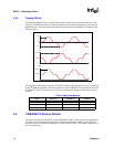
5.3.1 10BASE-T Manchester Decoder
The 82555 performs Manchester decoding and timing recovery when in 10 Mbps mode. The
Manchester encoded data stream is decoded from the receive differential pair to separate Receive
Clock and Receive Data lines from the differential signal. This data is transferred to the controller
at 2.5 MHz/nibble through the MII. The high-performance circuitry of the 82555 exceeds the IEEE
802.3 jitter requirements.
5.3.2 10BASE-T Twisted Pair Ethernet (TPE) Receive Buffer and Filter
In 10 Mbps mode, data is expected to be received on the receive differential pair after passing
through isolation transformers. The filter is implemented inside the 82555 for supporting single
magnetics that are shared with the 100BASE-TX side. The input differential voltage range for the