


Datasheet 45
Networking Silicon — 82555
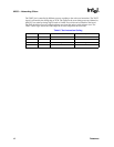
11.4 AC Characteristics
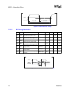
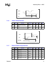
11.4.1 MII Clock Specifications
I
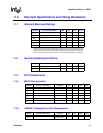
CC100
c
Current on all V
CC
pins 235 mA
I
CCT100TOT
Total supply current 275 mA
a. Transmitter current is measured with a 1:1 transformer on the center tap.
b. Transmitter current is measured with a 1:1 transformer on the center tap.
c. Current is measured on all V
CC
pins at V
CC
= 5.25 V.
Symbol Parameter Description Condition Min Typ Max Units
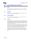
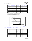
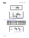
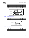
Figure 12. RBIAS100 Resistance versus I
CCT100
667
Ω
634
Ω
604
Ω
38mA 40mA
42mA
Icct100
Rbias100
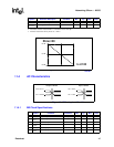
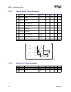
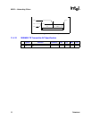
Figure 13. AC Testing Level Conditions
Output Levels Input Levels
V
IH
= 2.0 V
V
IL
= 0.8 VV
OL
= 0.45 V
V
OH
= 2.4 V
Symbol Parameter Conditions Min Typ Max Units
T1 T
P100
TXC/RXC period 100 Mbps 40 ns
T2 T
P10
TXC/RXC period 10 Mbps 400 ns
T3 T
PMDC
MDC clock period 400 ns
T4 T
TXDC
TXC duty cycle 35 65 %
T5 T
RXDC
RXC duty cycle 35 65 %
T6 T
MDC
MDC duty cycle 35 65 %