


46 Board Manual
Intel
®
IQ80321 I/O Processor Evaluation Platform
Hardware Reference Section
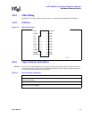
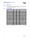
3.8.5 Mictor J3F2
Warning: Be sure to fully understand the pin assignments of the particular logic analyzer being used before
connecting to the Intel
®
IQ80310 Evaluation Platform Board. When voltage is applied, particularly
to a NC pin, hardware damage can be incurred.
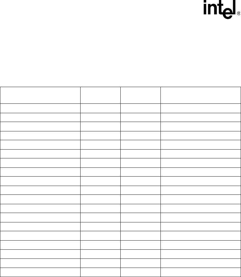
Table 18. Micor J3F2 Signal/Pins
Schematic Signal Name
Mictor Pin
Name
Mictor Pin
Name
Schematic Signal Name
FLASH_SEL/RST_MODE* 1 2 PB_AD<13>
ROT_SW_SEL* 3 4 PB_AD<14>
MSB_LED_DEL* 5 6 PB_AD<15>
LSB_LED_SEL* 7 8 PB_AD<16>
UART_SEL/RETRY* 9 10 PB_AD<17>
FLASH_SEL/RST_MODE* 11 12 PB_AD<18>
PB_AD<0> 13 14 PB_AD<19>
PB_AD<1> 15 16 PB_AD<20>
PB_AD<2> 17 18 PB_AD<21>
PB_AD<3> 19 20 PB_AD<22>
PB_AD<4> 21 22 PB_AD<23>
PB_AD<5> 23 24 PB_AD<24>
PB_AD<6> 25 26 PB_AD<25>
PB_AD<7> 27 28 PB_AD<26>
PB_AD<8> 29 30 PB_AD<27>
PB_AD<9> 31 32 PB_AD<28>
PB_AD<10> 33 34 PB_AD<29>
PB_AD<11> 35 36 PB_AD<30>
PB_AD<12> 37 38 PB_AD<31>