


37
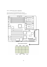
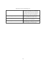
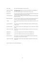
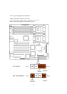
Power LED:
This 3-pin connector attaches to the power LED.
HDD Activity LED:
This 2-pin connector attaches to the LED of the hard disk. The LED lights up
when HDD is active.
Power Switch:
This 2-pin connector attaches to the power button of the system.
Reset Switch:
This 2-pin connector attaches to the case-mounted reset switch for rebooting your
computer without turning on/off your power switch.
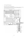
ACPI Sleep Switch:
This 2-pin connector connects to the switch that can take the system into standby
mode when pressed.
NMI to CPU Switch:
This 1-pin connector connects to the switch that send Non-Maskable Interrupt to
the CPU. User can customize the button to perform a particular function.
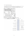
5 VSB: This connector provides the user with power to any extra devices that uses 5 volt
power.
Cooling Fault LED: This connector connects to the LED that lights up when a problem arises with
cooling system.
System Fault LED: This connector connects to the LED that lights up when a problem arises with the
system.
LAN#1 Activity LED: This connector connects to the LED that lights up when there is activity on the
LAN 1 port.
SMBus SDA: A private bus to BMC chip for serial data, for use with BMC only.
SMBus SCL: A private bus to BMC chip for serial clock, for use with BMC only.
Chassis Intrusion: This connects to the mechanical switch that indicates whether the chassis had
been opened. User can activate it if desired.
LAN#2 Activity LED: This connector connects to the LED that lights up when there is activity on the
LAN 2 port.
# Pin-27 to Pin-34 are reserved for OEM purpose