


56K V.92 Data, Fax, and Voice Chipset
Programmer’s Guide Intel Confidential 121
10.1 UART Register Definitions
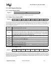
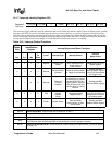
10.1.1 Scratch Register (SCR)
This is an 8-bit read/write register used by the DTE for temporary storage of data.
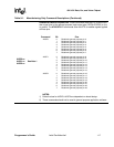
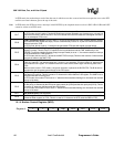
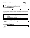
10.1.2 Modem Status Register (MSR)
This register provides four bits (bits 7:4) that show current modem state and four bits (bits 3:0) that provide modem change
information. Bits 3:0 are set to ‘1’ whenever the control information changes state. These bits are reset to “0” whenever the DTE
reads the MSR register. If the modem status interrupt is enabled (IER3), the modem generates an interrupt on the µP HINT pin
whenever MSR bits 3:0 are set to ‘1’.
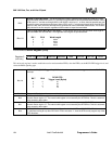
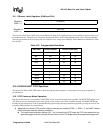
10.1.3 Line Status Register (LSR)
This read-only register provides UART status information to the host. Bits 4:1 report error conditions. These bits are reset to “0”
any time the host reads this register. An interrupt is generated to the host whenever any one of the bits (4:1) is set to “1” and the
RLSIE (receiver line status interrupt) has been enabled. Bits 0, 5, and 6 provide status information for sending and receiving data
through the THR (Transmit Holding register) and the RBR (Receiver Buffer register). Bits 0, 5, 6 are reset to ‘1’ only when the
host performs a specified action.
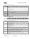
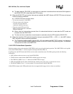
Bit 7
Data Carrier Detect (DCD)–When this bit is set to “1”, it indicates that the remote modem data carrier has
been detected (refer to the &C command).
Bit 6
Ring Indicate (RI)–This bit indicates when a ring signal has been detected.
Bit 5
Data Set Ready (DSR)–This bit indicates when the modem is ready to establish a communication link.
When entering voice mode, DSR is set to “1”. DSR is used for voice playback/record DMA mode to indicate
when the DTE has not responded to a modem DMA data transfer request. DSR is set to “1” when DMA data
are being transferred; DSR is set to “0” when a new DMA transfer has not occurred with 1.7 ms after the pre-
vious DMA transfer. DSR works similarly to a DMA terminal count.
Bit 4
Clear To Send (CTS)–When this bit is set to “1”, it indicates to the DTE that the modem is ready to receive
data.
Bit 3
Delta Data Carrier Detect (DDCDD)–When this bit is set to “1”, it indicates that the DCD bit has changed its
value since the DTE last read the MSR register.
Bit 2
Trailing Edge of Ring Indicator (TERI)–This bit is set to “1” after the RI signal goes from a high to low
state.
Bit 1
Delta Data Set Ready (DDSR)–When this bit is set to “1”, it indicates that the DSR bit has changed its value
since the DTE last read the MSR register.
Bit 0
Delta Clear to Send (DCTS)–When this bit is set to “1”, it indicates that the CTS bit has changed its value
since the DTE last read the MSR register.
SCRRegister 7
DCD RI DSR CTS DDCDD TERI DDSR DCTS
Register 6
RCVR Err TEMT THRE BI FE PE OE DR
Register 5