56K V.92 Data, Fax, and Voice Chipset
Programmer’s Guide Intel Confidential 83
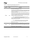
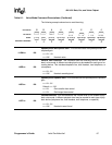
+VBT=m see “m”
Buffer Threshold Setting: This command specifies the flow control assert and
deassert points inside the DCE’s internal transmit buffer. The internal buffer is
512 bytes. The +VBT=m parameters are fixed in firmware and cannot be
changed.
m = <deassert>, <assert>
Defaults: <deassert> = 192, <assert> = 320
<assert>: This parameter stops data transfer from the DTE when the number of
bytes in the buffer reaches the lower number of the range specified by the <as-
sert> parameter. So that no data is lost before the modem stops the flow of data,
the <assert> parameter allows more data to enter the buffer until it reaches the
larger number in its range.
Range: <assert> = 192
<deassert>: This parameter starts data transfer from the DTE after the number
of bytes in the transmit buffer falls below the <deassert> value.
Range: <deassert> = 320
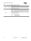
+VCID=n 0
Caller ID Selection: This command controls the reporting and presentation of
data in the ICLID (Incoming Call Line ID) data format used by the Caller ID ser-
vices in the United States and Canada. At a minimum, the data sent to the DCE
includes the date, time, and the caller’s telephone number. Caller ID information
is sent to the DTE during the first and second ring signals when the modem is in
voice, data, or fax mode.
n = 0–2
n = 0* Disables Caller ID
n = 1 Enables Caller ID with formatted presentation to the DTE. The
modem presents the data items in a <Tag><Value> pair format.
The expected pairs are data, time, caller code (phone number),
and name.
n = 2 Enables Caller ID with unformatted presentation to the DTE. The
modem presents the entire packet of information, excluding the
leading U’s, in ASCII-printable hex numbers.
Note: If S0=1 (auto-answer mode) and Caller ID is enabled in data modem
mode, then the modem answers only after the second ring signal.
Table 6-1. Voice Mode Command Descriptions (Continued)


