


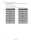

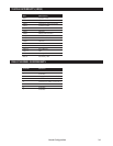
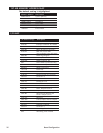

External Switches and Indicators (CN7)
There are several external switches and indicators for monitoring and controlling
the CPU board. All the functions are in the CN7 Multi Panel connector. For the lo
-
cation of this connector, refer to figure 2.
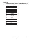
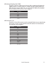
USB Port Connector (CN9)
The SBC-370 has two built-in USB ports for future I/O bus expansion. Pins 1, 3, 5,
and 7 for USB 0. Pins 2, 4, 6, and 8 for USB 1. For the location of this connector,
refer to figure 2.
Pin Number Description
1VCC
3 SBD0-
5 SBD0+
7 GND
2 GND
4 SBD1+
6 SBD1-
8VCC
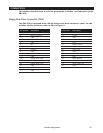
21 Board Configuration
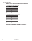
Pin Number Description
1 SPEAKER
2 VCC
3NC
4NC
5NC
6 GND
7 +5V
8 KEYLOCK
9 RESET SW
10 GND
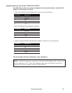
Pin Number Description
11 GND
12 GND
13 IDE LED
14 NC
15 +5V
16 ATX POWER CONTROL
17 ATX POWER BUTTON
18 ATX 5VSB
19 ATX 5VSB
20 ATX 5VSB