


Table of Contents
1. Features. . ..............................6
OVERVIEW .................................................6
Feature LIST .................................................6
CPU...................................................6
SDRAM .................................................6
AGP VGA Controller...........................................7
Ethernet Controller ...........................................7
Ultra DMA/33 Enhanced PCI EDI Interface ...............................7
Multi-I/O Chip .............................................7
Floppy Disk Drive Interface .......................................7
Two High Speed Series Ports.......................................7
Parallel Port ...............................................7
Hardware Monitoring System ......................................8
IrDAPort................................................8
USBPort.................................................8
ISAPLUS .................................................8
E2Key™.................................................8
Watchdog Timer.............................................8
Flash Disk - DiskOnChip™........................................8
ATX Power Supply Function .......................................8
Power Consumption...........................................8
Operating Humidity ...........................................9
Watchdog Timer...............................................9
E
2
KEY™ FUNCTION .............................................9
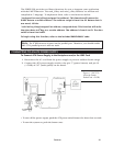
Connecting to an ATX Power Supply ....................................10
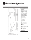
2. Board Configuration .........................12
Board Layout ................................................12
Jumpers ..................................................13
CPU Frequency Setting (JP3) ......................................13
CPU Multiplier Setting (JP8) ......................................13
Watchdog Timer Type Setting (JP5) ..................................13
Watchdog Timeout Period (JP12)....................................14
DiskOnChip™ Memory Address Setting (JP11).............................14
Clear CMOS Setup (JP4) ........................................14
PS/2 Mouse Setting (JP7) .......................................15
Connectors .................................................16
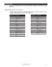
Floppy Disk Drive Connector (CN2) ..................................16
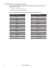
PCI E-IDE Disk Drive Connector (CN1/CN3) ..............................17
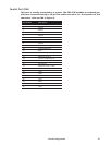
Parallel Port (CN4) ...........................................18
Serial Ports (CN12/CN11) .......................................19
Keyboard/Mouse Connector (CN8/CN17/CN18) ...........................20
External Switches and Indicators (CN7) ................................21
USB Port Connector (CN9) .......................................21
IrDA Infrared Interface Port (CN6) ...................................22
VGA Connector (J1) ..........................................22
LAN RJ45 Connector (CN10)......................................23
3