


54
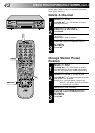
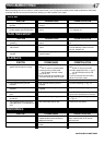
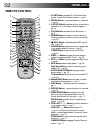
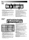
1 and 2 Symbolic Mode Indicators
* The indicator will blink during turbo search.
3 "DAILY" Program Mark lights when recorder has been
programmed to record daily serial.
੬ pg. 29
4 "WEEKLY" Program Mark lights when recorder has
been programmed to record weekly serial.
੬ pg. 29
5 Start Time/Stop Time Indicator separates Start Time
and Stop Time of timer recording on Display Panel.
੬ pg. 29
6 Tape Remaining Time Indicator displays time remaining
on tape when certain buttons are pressed.
੬ pg. 16
7 PDC Indicator lights when PDC has been engaged
for timer recording.
੬ pg. 33
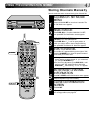
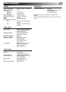
PLAY:
STILL:
FORWARD SLOW:
FF:
STILL:
REVERSE SLOW:
REW: RECORD:
FF VARIABLE
RECORD PAUSE:
SHUTTLE SEARCH:
REW VARIABLE
AUDIO DUBBING:
SHUTTLE SEARCH:
REVERSE PLAY:
AUDIO DUBBING
PAUSE:
REAR
VIEW
DISPLAY
PANEL
PAUSE/
R.A.EDIT
AV2 IN
RF OUT
RF OUT
ON–TEST–OFF
32
40
ANT. IN
AV1 IN/OUT
R
L
AUDIO OUT
13
5
76
8
9
42
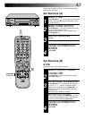
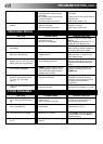
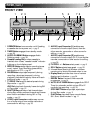
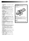
6 RF OUT Switch enables operation via RF connection
or AV connection; activates test pattern when tuning
TV receiver for video preset.
੬ pg. 5
7 Remote PAUSE/R.A. EDIT Connector enables
connection to second recorder equipped with
Remote PAUSE or R.A. EDIT Connector, or to JVC
camcorder equipped with Master Edit Control, for
easy editing.
੬ pg. 35
8 RF OUT Connector enables connection to aerial
terminal of TV receiver.
੬ pg. 4
9 RF Output Channel Adjustment Screw enables
adjustment of output channel if UHF channel 36 is
used in your area.
੬ pg. 5
1 Mains Power Cord supplies power to recorder.
੬ pg. 4
2 AUDIO OUT (L/R) Connectors enable connection of
audio cassette recorder, TV or second video recorder
for dubbing.
੬ pg. 7
3 AV1 IN/OUT SCART Connector enables AV connec-
tion to TV or second recorder; input recordable when
"AU 1" selected.
੬ pg. 4
4 AV2 IN Connector enables connection of satellite
receiver or second recorder; input recordable when
"AU 2" selected.
੬ pg. 6
5 ANT. IN Connector enables connection of aerial.
੬ pg. 4
M
D
SP
LP
EP
D
I T R
W
+8
4
0
6
10
–20dB
NORM
L1 2
R
REMAIN
9@0 # $
1
25
6347
8
! %
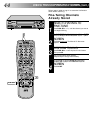
8 B.E.S.T. Picture System Display lights from bottom to
top while B.E.S.T. is active.
੬ pg. 21
Audio Level Indicator displays audio input and
output levels.
9 "Cassette Loaded" Mark lights once a cassette is
inserted; remains lit until cassette ejected or power
turned off.
0 Instant Timer Recording Indicator lights when ITR
initiated; remains lit until ITR finishes.
੬ pg. 25
! Tape Speed Indicators display mode of recording; light
during Record or Play mode.
੬ pg. 20
@ "Timer" Indicator lights when TIMER has been
pressed to engage Timer mode.
੬ pg. 29
# Counter shows time elapsed since playback or
recording began.
REMAIN displays time remaining from current tape
position to end of tape.
Clock Display shows current time.
੬ pg. 9
* Counter, REMAIN and Clock Display appear
alternately when DISPLAY is pressed.
$ Channel Display shows station name being received
and its preset position.
Mode shows external input mode selected.
% Audio Mode Indicator displays audio output mode
currently selected.
*
*