


6
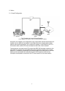
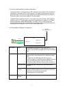
3.2. Outline of Host Station (Transmitter) Operations
The host station is configured using a transceiver and a PC connected to the network.
Data signals that control the transceiver are connected to the PC using either LAN, USB
or RS-232C. The PC uses its sound function to input and output audio transmitted and
received by the transceiver, and converts them between digital and analog signals.
The ARHP-990 is installed on the PC. In the case of use via the internet, VoIP Program is
installed on the PC. The ARHP-990 exchanges transceiver control data signals with the
network. The VoIP Program exchanges audio transmissions with the network.
The PC is connected to the network, and exchanges transceiver control data signals and
audio transmissions with the "Remote station (operator)" on the network.
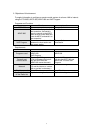
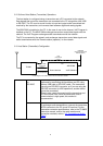
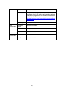
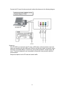
3.3. Host Station (Transmitter) Configuration
TS-990
PC
Sound devices
ARHP-990
VoIP Software
USB/RS-232C
(Transceiver
control)
LAN/WAN
(Commnunication with
Remote Station)
LAN
(Transceiver
control)
Audio transmission
�
In this diagram, the modem, router, and hub have been omitted.
�
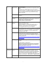
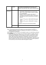
Connection
LAN, USB
or
RS-232C
Controls that change the frequency or mode are
performed by connecting the transceiver and PC using
either a USB cable or RS-232C cable. (The transceiver
has only one RS-232C connector, so if you are using the
RS-232C connector for KNS operations, another device
cannot be connected.)
There is also a way to connect both the transceiver and
PC to the home LAN. Since the transceiver control
communication is high-speed, this method is
recommended.
Audio
The audio cable is created by the user.
To exchange audio transmissions, connect the transceiver
ACC2 connector to the PC sound I/O terminal. For the
transceiver connector specifications, refer to the TS-990S
instruction manual, and for the cable creation and
connection methods, refer to "
4.2. Connecting an Audio
Cable".