


Table 6. System board jumpers (continued)
Jumper number Jumper name Jumper setting
Notes:
1. If no jumper is present, the server responds as if the pins are set to 1 and 2.
2. Changing the position of the UEFI boot recovery jumper from pins 1 and 2 to pins 2 and 3 before the server is
turned on alters which ash ROM page is loaded. Do not change the jumper pin position after the server is
turned on. This can cause an unpredictable problem.
Important:
1. Before you change any switch settings or move any jumpers, turn off the server; then, disconnect all
power cords and external cables. Review the information in “Guidelines for trained service technicians”
on page 115, “Handling static-sensitive devices” on page 117, and “Turning off the server” on page 113.
2. Any system-board switch or jumper blocks that are not shown in the illustrations in this document
are reserved.
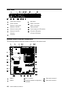
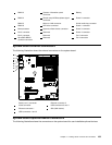
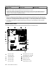
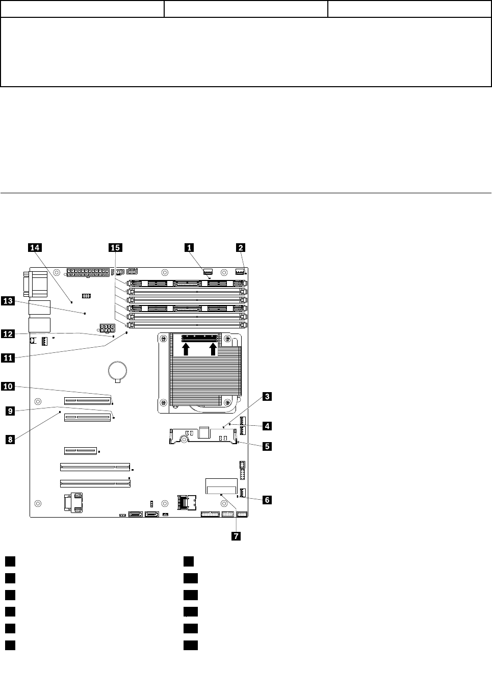
System-board LEDs
The following illustration shows the light-emitting diodes (LEDs) on the system board.
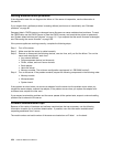
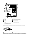
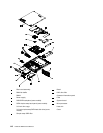
Heatsink
Orientation
DIMMs
DIMMs
1
Fan 5 error LED
9
PCI Express slot 2 error LED
2
Fan 4 error LED
10
PCI Express slot 1 error LED
3
H8 Heartbeat LED
11
Microprocessor error LED
4
Fan 3 error LED
12
Battery error LED
5
Fan 2 error LED
13
Standby power LED
6
Fan 1 error LED
14
System board error LED
112 Hardware Maintenance Manual