


1
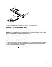
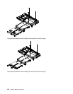
PCI-X power cable
2
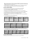
PCI-X slot
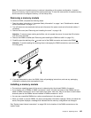
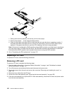
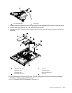
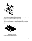
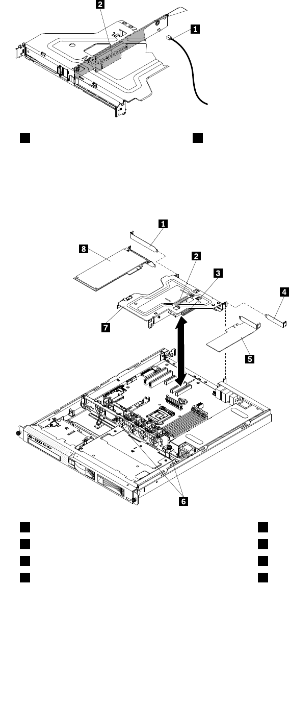
7. Grasp the riser-card assembly at the front grip point and rear edges and lift to remove it from the server.
8. Place the riser-card assembly on a at, static-protective surface.
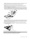
9. Carefully grasp the PCI card by its top edge or upper corners, and pull the PCI card from the riser-card
assembly.
00
00
00
00000000
00000000
00000000
00000000
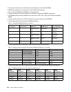
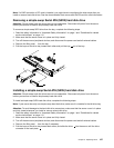
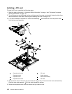
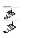
1
Expansion-slot cover
5
PCI card
2
Expansion slot 2
6
Guide channels
3
Expansion slot 1
7
Riser-card assembly
4
Expansion-slot cover
8
PCI card
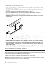
10.If you are instructed to return the PCI card, follow all packaging instructions, and use any packaging
materials for shipping that are supplied to you.
11.Go to “Completing the FRU replacement” on page 172.
Chapter 6. Replacing FRUs 131