


• Follow the suggested actions in the order in which they are listed in the Action column until the problem is
solved.
• See Chapter 7 “Parts listing, RS210 Types 6531, 6532, 6533, and 6534” on page 175 to determine which
components are customer replaceable units (CRU) and which components are eld replaceable units (FRU).
• If an action step is preceded by “(Trained service technician only),” that step must be performed only by
a trained service technician.
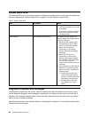
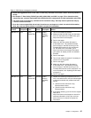
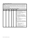
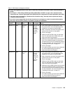
Component LED Description Action
PCI slots error LEDs An error has occurred on a PCI
bus or on the system board. An
additional LED is lit next to a failing
PCI slot.
1. Check the system-event log for information about
the error.
2. If you cannot isolate the failing adapter through the
LEDs and the information in the system-event log,
remove one adapter at a time, and restart the server
after each adapter is removed.
3. If the failure remains, go to
http://www.lenovo.com/support for additional
troubleshooting information.
Enclosure manager
heartbeat LED
power-on and power-off
sequencing.
1. If the LED ashes at 1Hz, it is functioning properly
and no action is necessary.
2. If the LED is not ashing, (trained service technician
only) replace the system board.
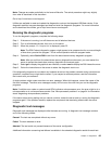
Power-supply LEDs
The following minimum conguration is required for the DC LED on the power supply to be lit:
• Power supply
• Power cord
The following minimum conguration is required for the server to start:
• One microprocessor in microprocessor socket 1
• One 1 GB DIMM on the system board
• One power supply
• Power cord
• ServeRAID SAS/SATA adapter
• Five cooling fans
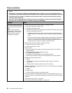
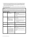
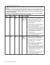
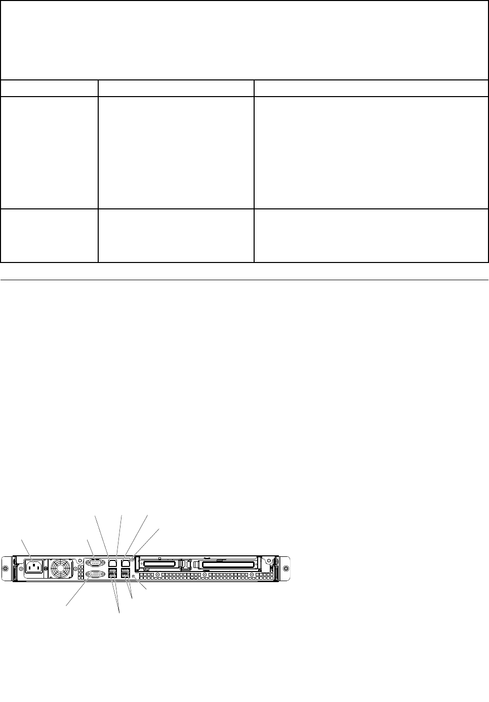
The following illustration shows the locations of the power-supply LEDs.
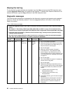
Power-cord
connector
USB1-2 connector
USB3-4 connector
Serial
connector
Video
connector
Ethernet1
activityLED
Ethernet1
linkLED
Ethernet2
activityLED
Ethernet2
linkLED
NMIbutton
Chapter 4. Diagnostics 63