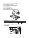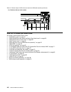
• “1050 Hard disk drive or solid state drive assembly” on page 62
• “1110 Wireless WAN slot cover and PCI Express Mini Card for wireless WAN” on page 71
• “1110 mSATA solid state drive” on page 73
• “1120 Palm rest assembly with cables” on page 74
• “1130 PCI Express Mini Card for wireless LAN” on page 78
• “1160 Media Card Reader slot board and Media Card Reader cable assembly” on page 81
• “1170 Keyboard” on page 83
• “1180 Keyboard bezel” on page 85
• “1190 LCD unit” on page 87
• “2010 Top shielding assembly” on page 90
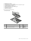
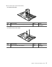
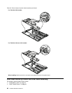
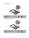
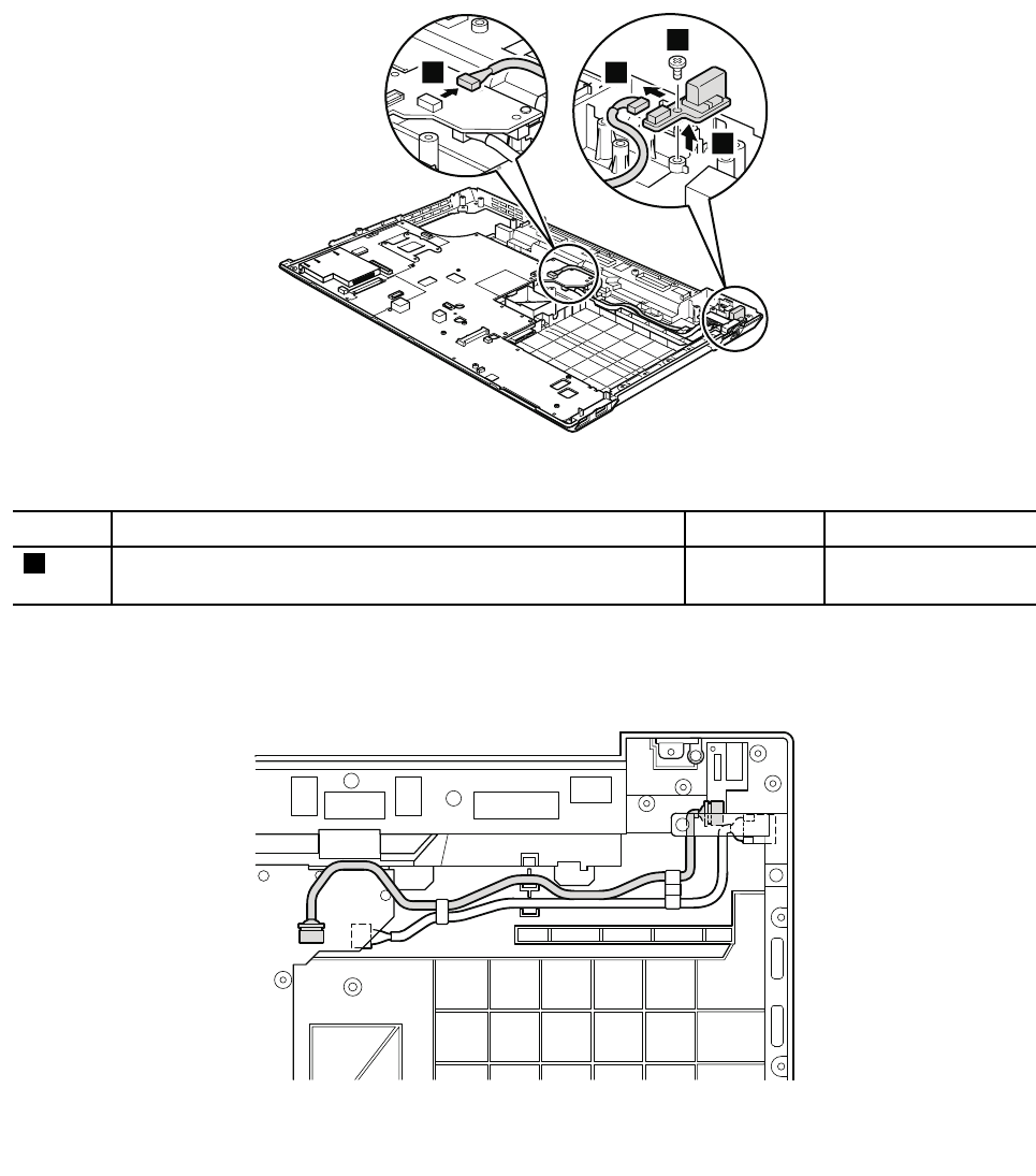
Table 31. Removal steps of USB connector board and USB cable assembly
3
2
4
1
When installing: Make sure that the connectors are attached rmly.
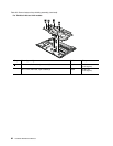
Step Screw (quantity) Color
Torque
2
M2 × 3 mm, at-head, nylon-coated (1)
Black 0.181 Nm
(1.85 kgfcm)
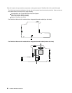
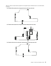
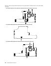
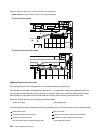
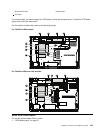
Cable routing: Route the USB cable assembly as shown in the following gures.
For ThinkPad L520 models:
Chapter 8. Removing and replacing a FRU 99


