


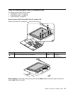
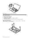
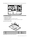
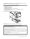
When installing: Route the cables as shown in the following illustration before you attach the keyboard bezel.
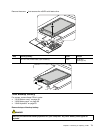
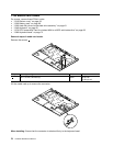
1110 Speaker assembly
For access, remove these FRUs in order:
• “1010 Bottom cover” on page 58
• “1020 Battery pack” on page 60
• “1030 Hard disk drive or solid-state drive assembly” on page 61
• “1040 Keyboard” on page 63
• “1070 PCI Express Mini Card for wireless WAN or mSATA solid-state drive” on page 68
• “1090 Keyboard bezel” on page 72
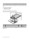
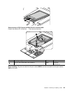
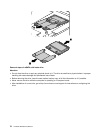
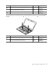
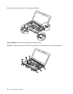
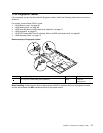
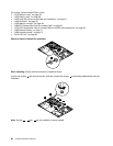
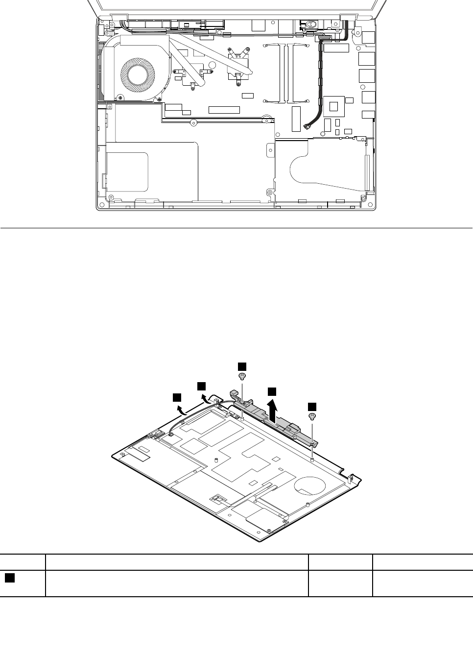
Removal steps of speaker assembly
1
1
3
2
2
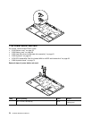
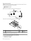
Step Screw (quantity) Color
Torque
1
M2 × 3.0 mm, wafer-head, nylon-coated (2)
Black 0.181 Nm
(1.85 kgf-cm)
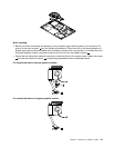
When installing: Ensure that the connector is attached rmly.
Chapter 9. Removing or replacing a FRU 75