


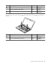
For access, remove these FRUs in order:
• “1010 Bottom cover” on page 58
• “1020 Battery pack” on page 60
• “1030 Hard disk drive or solid-state drive assembly” on page 61
• “1040 Keyboard” on page 63
• “1050 Memory module” on page 66
• “1060 PCI Express Mini Card for wireless LAN” on page 67
• “1070 PCI Express Mini Card for wireless WAN or mSATA solid-state drive” on page 68
• “1080 Backup battery” on page 71
• “1090 Keyboard bezel” on page 72
• “2010 LCD unit” on page 84
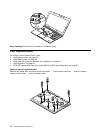
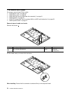
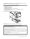
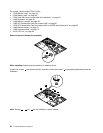
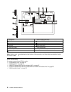
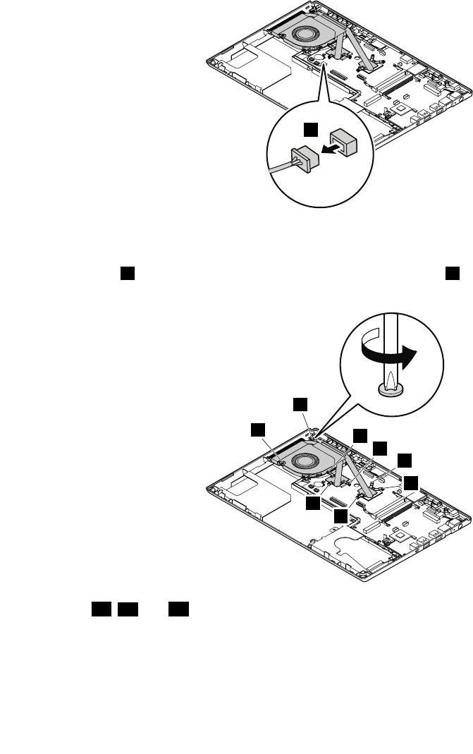
Removal steps of thermal fan assembly
1
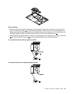
When installing: Ensure that the connector is attached rmly.
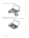
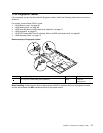
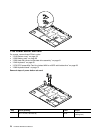
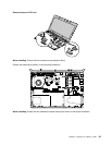
Loosen the screws
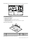
2 that secures the fan, and then loosen the screws 3 in ascending alphabetical order as
illustrated.
2
3f
3e
3c
3b
3d
3a
2
Note: Screws 3d , 3e and 3f are not available on some models.
80 Hardware Maintenance Manual