


7
Product Overview
Business Series Smart Gigabit Ethernet Switch
Chapter 2
SLM224P
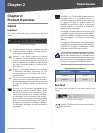
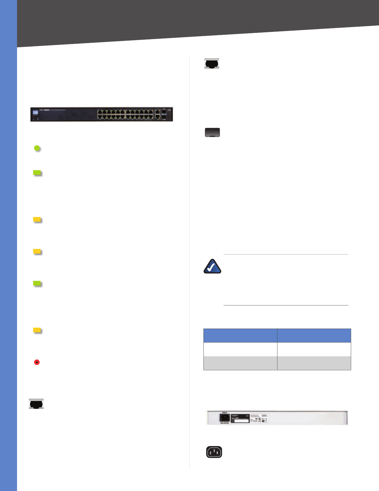
Front Panel
The Switch’s LEDs and ports are located on the front
panel.
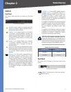
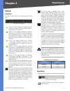
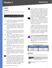
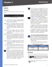
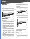
Front Panel of the SLM224P
SYSTEM (Green) Lights up to indicate that the
Switch is powered on. Blinks while the Switch is
performing a system self-test.
LNK/ACT (1-24) (Green) Lights up to indicate
a functional 10/100 Mbps network link through
the corresponding port (1 through 24) with
an attached device. Blinks to indicate that the
Switch is actively sending or receiving data over
that port.
PoE (1-6, 13-18) (Amber) Blinks to indicate that
power is being supplied to an attached powered
device (PD) on the corresponding port (1 through
6, 13 through 18).
100M (7-12, 19-24) (Amber) Lights up to
indicate a functional 100 Mbps connection on
the corresponding port (7 through 12, 19 through
24) with an attached device.
LNK/ACT (G1-G2) (Green) Lights up to indicate
a functional 10/100/1000 Mbps network link
through the corresponding port (G1 through G2)
with an attached device. Blinks to indicate that
the Switch is actively sending or receiving data
over that port.
Gigabit (G1-G2) (Amber) Lights up to indicate
a functional 1000 Mbps connection on the
corresponding port (G1 through G2) with an
attached device.
Reset To reboot the Switch, press and hold the
Reset Button for approximately five seconds. To
reset the Switch settings to the factory defaults,
press and hold the Reset Button for approximately
ten seconds.
Ethernet 1-24 The Switch is equipped with 24
auto-sensing, Ethernet network ports, which
use RJ-45 connectors. The Fast Ethernet ports
support network speeds of 10 Mbps or 100 Mbps.
They can operate in half- and full-duplex modes.
Auto-sensing technology enables each port to
automatically detect the speed of the device
connected to it (10 Mbps or 100 Mbps), and
adjust its speed and duplex accordingly.
G1-G2
The Switch is equipped with 2 auto-
sensing Gigabit Ethernet network ports, which
use RJ-45 connectors. The Gigabit Ethernet ports
support network speeds of 10 Mbps, 100 Mbps, or
1000 Mbps. They can operate in half- and full-duplex
modes. Auto-sensing technology enables each port
to automatically detect the speed of the device
connected to it (10 Mbps, 100 Mbps, or 1000 Mbps),
and adjust its speed and duplex accordingly.
miniGBIC (1-2) The miniGBIC (gigabit interface
converter) port is a connection point for a
miniGBIC expansion module, so the Switch can
be uplinked via fiber to another switch. The
MiniGBIC port provides a link to a high-speed
network segment or individual workstation at
speeds of up to 1000 Mbps.
To establish a Gigabit Ethernet connection using
a miniGBIC port, you will need to install a MGBT1,
MGBSX1, or MGBLH1 Gigabit expansion module
and use Category 5e cabling or fiber optic cabling.
To establish a Fast Ethernet connection using a
miniGBIC port, you will need to install a MFEFX1
(100BASE-FX) or MFELX1 (100BASE-LX) 100SFP
Transceiver and use fiber optic cabling.
NOTE: On the SLM224P, MiniGBIC ports are
shared with Gigabit Ethernet ports. If a miniGBIC
port is used, then the shared Gigabit Ethernet
port on the Switch cannot be used. The following
table defines the shared port mapping of the
SLM224P Switch.
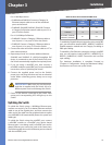
SLM224P Shared Port Mapping
miniGBIC Port Gigabit Port
miniGBIC 1 Port G1
miniGBIC 2 Port G2
Back Panel
The power port is located on the back panel of the Switch.
Back Panel of the SLM224P
POWER The Power port is where you connect
the AC power.