Chapter 4
Configuration Using the Web-based Utility
11
Business Series Smart Gigabit Ethernet Switch
Chapter 4:
Configuration Using the
Web-based Utility
This chapter describes the features included in the Web-
based Utility. All features shown in this chapter, unless
specifically identified, are included in the all of Smart
Switches. Unique features for specific Switches are noted.
NOTE: The web-based utility is optimized for
a screen resolution of 1024 x 768. Internet
Explorer version 5.5 or above is recommended..
To use the utility, open your web browser, enter
http://192.168.1.254 in the Address field, then press Enter.
Address Bar
NOTE: The default IP address is 192.168.1.254.
If you have changed the IP address or are using
DHCP to assign it, enter the new IP address
instead. The computer you use for configuration
should be on the same subnet as the Switch.
The Login screen appears. Enter admin in the Username
field and enter the password in the Password field. If this is
the first time you are using the utility, leave the Password
blank. Then press OK to log in. The Setup tab’s Summary
screen appears.
(After you have completed your first login, f
or security
purposes it is recommended that you set a password at
a later time. For detailed information on changing the
password, refer to section “Admin > User Authentication.”
)
Login Screen
Each time you log in, the web-based utility first displays
the Setup tab’s Summary screen. To access another screen,
you first select the appropriate category from among the
10 tabs that appear at the top of the screen: Setup, Port
Management, VLAN Management, Statistics, Security,
QoS, Spanning Tree, Multicast, Admin, and Logout.
Then, select the desired screen from the list directly below
the tab names.
Setup
The Setup tab contains the Summary screen. This screen
displays basic system information.
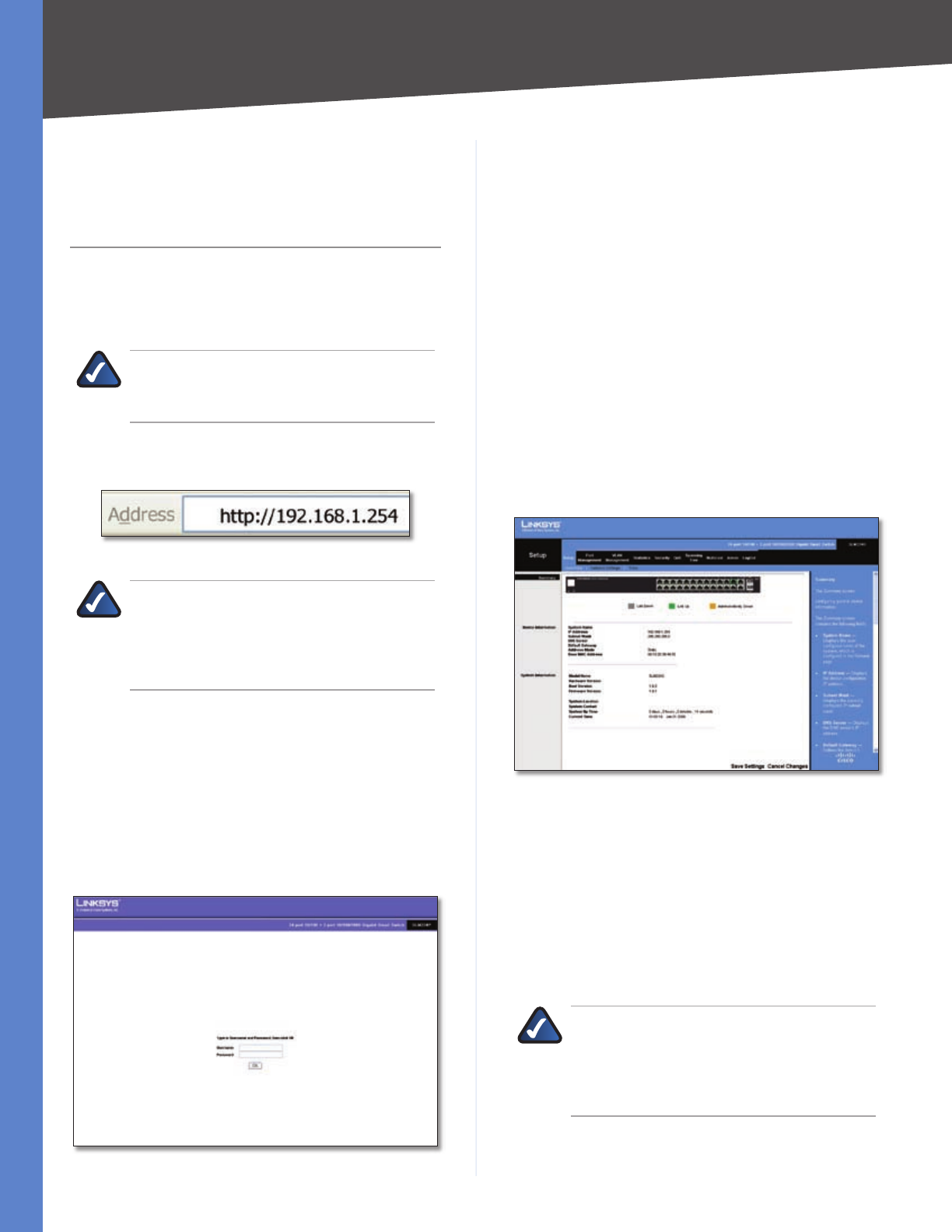
Setup > Summary
The Summary screen displays a summary of Switch
information. The settings shown cannot be modified
from the Summary screen; however, many of them can be
modified from the Setup tab’s Network Settings screen.
Setup > Summary
At the top of the Summary screen, an image of the Switch‘s
front panel provides the following color-coded status
information for the Switch’s Ethernet ports:
Green Indicates that the port has a connection.
Gray Indicates that the port has no connection.
Orange Indicates that the port has been closed down by
the administrator.
Click on a port to display that port’s statistics.
NOTE: The port colors in the Summary screen
are not related to the colors of the LEDs on the
Switch’s ports. The port LEDs display different
status information, as described in “Chapter 2:
Overview.”
The Summary screen two sections: Device Information and
System Information. These are described below.


