


10
Installation
Business Series Smart Gigabit Ethernet Switch
Chapter 3
For a 1000 Mbps device:
SLM2048 and SLM2024: Connect a Category 5e
Ethernet network cable to one of the numbered
ports on the Switch.
SLM248G, SLM248P, SLM224G, SLM224P: Connect
a Category 5e Ethernet network cable to port G1 or
port G2 on the Switch.
For a 10/100 Mbps PoE device:
SLM248P: Connect a Category 5 Ethernet cable to
one of ports 1-12 or ports 25-36 on the Switch.
SLM224P: Connect a Category 5 Ethernet cable to
one of ports 1-6 or ports 13-18 on the Switch.
Connect the other end of the network cable to a PC or
other network device.
Repeat steps 2 and 3 to connect additional devices.
SLM248P and SLM224P: If a 802.3af-compliant PoE
device is connected to one of the Switch’s PoE ports,
the Switch automatically supplies the required power.
If you are using a miniGBIC port, then connect a
miniGBIC module to a miniGBIC port. For more detailed
instructions, refer to “Uplinking the Switch“.
Connect the supplied power cord to the Switch’s
power port, and plug the other end into an electrical
outlet. When connecting power, always use a surge
protector.
IMPORTANT: Make sure you use the power
cord that is supplied with the Switch. Use of a
different power cord could damage the Switch.
Power on the devices connected to the Switch. Each
active port’s corresponding LED will light up on the
Switch.
Uplinking the Switch
To uplink the Switch using a 1000 Mbps Ethernet port,
connect one end of a Cat 5e (or better) Ethernet network
cable to one of the Gigabit ports, and then connect the
other end of the cable into the peripheral device’s uplink
port. MDI/MDIX will automatically detect the speed and
cable type.
To uplink the Switch using the miniGBIC port, connect
a miniGBIC module to a miniGBIC port whose shared
Ethernet port is not being used (a miniGBIC port and its
shared Ethernet port cannot be used at the same time).
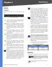
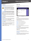
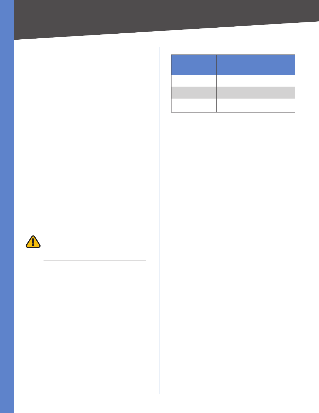
The following table shows which Ethernet ports are shared
with the miniGBIC ports.
•
•
•
•
3.
4.
5.
6.
7.
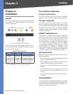
Ethernet Ports Shared with miniGBIC Ports
Switch
Port Shared
with
miniGBIC1
Port Shared
with
miniGBIC2
SLM2048 24 48
SLM2024 12 24
SLM248G, SLM248P,
SLM224G, SLM224P
G1 G2
To establish a Gigabit Ethernet connection using a miniGBIC
port, you will need to install a MGBT1, MGBSX1, or MGBLH1
Gigabit expansion module and use Category 5e cabling or
fiber optic cabling.
To establish a Fast Ethernet connection using a miniGBIC
port, you will need to install a MFEFX1 (100BASE-FX) or
MFELX1 (100BASE-LX) 100SFP Transceiver and use fiber
optic cabling.
The hardware installation is complete. Proceed to
“Chapter 4: Configuration Using the Web-based Utility”,
for directions on how to set up the Switch.