


PRACTICE 553 -2201-184
2. DESCRIPTION
FUNCTlONS
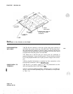
2.01 The SL-1 and console line circuit packs each contain eight line
circuits (see Fig.
2-l).
The SL-1 line pack can use all eight circuits,
each circuit interfacing to an SL-1 set. The console line pack uses pairs
of line circuits to interface to attendant consoles: one pair may be used
from the upper four circuits and one pair from the lower four to
interface to two consoles.
Note: Line circuits on the SL-1 line pack are automatically
powered up during signaling and transmission. The connected
circuit pairs on the console line pack are continuously powered on.
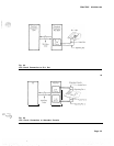
2.02 For SL-1 set connections. one pair of wires is used
for+
transmission and a second pair for signaling (see Fig. 2-2). For
attendant console connections, two pairs of wires are used for
transmission connections and two pairs for signaling connections. These
connec Lions:
(a) terminate the loop tip and ring conductors with a balanced
600-ohm termination:
(b)
provide
~15
V power, phantomed over the transmission and
signaling pairs, to the set or console terminals:
(c)
provide a measure of isolation of foreign potentials on the loop
from portions of the transmission and signaling circuitry;
(d)
convert from the 2-wire transmission path of the loop to a 4-wire
transmission path:
(e)
provide analog-to-digital and digital-to-analog conversion
_qf
transmission signals.
2.03 The circuit pack includes two common multiplexing circuits to:
(a) interface the individual line circuits with the peripheral bus
signaling channel:
(b)
retime digital signals received from the peripheral bus;
(c)
decode address information received from the peripheral bus and
enable individual line circuits during selected time slots.
2.04 The information and signaling relevant to the SL-1 set or console
passes through the line circuit pack and is multiplexed with information
from other circuit packs. A multiplex loop connects the input and
output of up to two Peripheral Equipment
(PE)
shelves to the Common
Equipment
(CE)
where switching takes place (see Fig. 2-2 and 2-3).
PHYSICAL
2.05 The line circuits and common circuitry of the pack are mounted
DESCRIPTION
on a 12.5 in
(320-mm)
by 10 in
(254-n&
printed circuit board. The
front of the pack is equipped with two pack extractors and a Light
Emitting Diode
(LED).
The rear of the pack is equipped with a
connector capable of accepting 80 pins. Ten of these circuit packs may
be mounted in one PE shelf but not to exceed 50% of the packs in a
cabinet.
Page 2-l
3 Pages
Revised, 85 06
: