


PRACTICE
553-2201-184
4. OPERATION WITH
SL-1
SET
CALL ORIGINATED
FROM AN SL-1 SET
I
/
.
.
_
,
-:
I
.
.
7.’
..!,
,_.,..-,..
:
IDLE CIRCUIT STATES
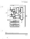
4.01
SL-1
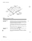
Set On-Hook. Multiplex control generates and sends scan
message to SL-1 set (2.5 ms message every 10 ms). Message is sent via
the signaling pair and hybrid transformer (Fig. 4-l).
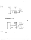
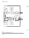
(1) Message detected by Scan and Signal Distributor
@SD).
(See Fig.
4-2 and 4-3.)
(2)
No message is being sent to line circuit on signaling pair.
(3) In time slot 0, CE scans each line circuit on loop in sequence,
detecting any change in signaling on the data input bus.
(4) Line circuit 0 is enabled in time slot 0. Signaling on data output
bus indicates that CE is ready to receive data.
(5)
No message on data input bus to CE indicates line circuit 0 is idle.
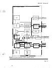
4.02 Originating the Call. SL-1 is off-hook (key operated). Off-hook
is detected by SSD in SL-1 set.
(1)
SSD sends off-hook signaling to line circuit on signaling pair at
2.37K
bit/s when scanned by message from multiplex. control.
(2)
Off-hook message from line circuit 0 is multiplexed with messages
from other line circuits and sent at a rate of 64K bit/s to the CE.
(3)
(4)
(5)
CE line scan detects change in signaling for line circuit 0.
CE line scan stops.
For the next 31 times, time slot 0 signaling message is sent-to CE
on data input bus from line circuit 0, then line scan continues.
(6)
CE detects signaling from line circuit 0 and determines circuit
number (TN number).
(7)
(8)
CE assigns message time slot to line circuit from time slots 2
through 31.
Signaling from CE is applied to the SL-1 set or console on
signaling pair. Rate is changed from 64K bit/s to
2.37K
bit/s by
multiplex control.
(9)
Signaling is detected by SSD.
(10) SL-1 set directory number lamp is lit.
(11) PCM codec is enabled during message time slot assigned by CF.
(12)
Dial tone on the data output bus is applied to SL-1 set via
multiplex control, PCM
codec,
digital-to-analog filter, hybrid
transformer and audio pair (during message time slot).
(13)
Dialed information from SL-1 set on signaling pair is applied to
the data input bus during time slot 0 (signaling).
Page 4-l
6
Pages