


Operation
page 2 —15
Users Manual
For complete protection, the upstream circuit breaker(s) supplying the UPS should be opened, locked, and tagged
while the UPS is being serviced. The UPS is now isolated for maintenance.
NOTE: This will dump any load being serviced even through the Bypass.
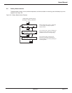
To restart the UPS after maintenance:
1. Close all the upstream circuit breakers supplying the UPS. Close the input isolation circuit breaker Q1.
2.
Close the circuit breaker Q4S. The UPS fans will start. Verify that the UPS is on bypass.
3. Depress transfer initiate switch. Unlock and remove the key from key interlock.
4. Insert the key into Q5N and unlock. Close the UPS isolation circuit breaker Q5N.
5. Open the maintenance bypass circuit breaker Q3BP and lock open. Remove the key.
6. Insert the key into the key interlock and turn to lock.
7. Wait for the green LED “B” on the hidden panel to turn on (indicating that the rectifier/battery charger has
started), then close the battery disconnect circuit breaker QF1. If there is more than one battery cabinet in your
configuration, close all the battery disconnect circuit breakers.
8. Automatic restart of the UPS is the normal configuration; the UPS inverter will start automatically and resume
normal operation. If your EPS 7000 has been programmed NOT to automatically restart, start the inverter by
pressing the “inverter on” pushbutton on the UPS front panel. The inverter will start and the UPS will resume
normal operation. If the transfer conditions are not satisfied (bypass out of tolerance or other reason), a forced
transfer will be required. Refer to section 2.12, Forced Transfers.
2.11.4 Without Maintenance Bypass
This procedure assumes that the UPS is operating normally, with the attached load supplied via the UPS inverter.
1. Stop the inverter by pressing the “inverter off” pushbutton on the UPS front panel for 3 seconds. The audible
alarm will sound; silence the alarm by pressing the audible alarm reset pushbutton on the hidden panel (see
Figure 1-8). If the transfer conditions are not satisfied (bypass out of tolerance or other reason), a forced
transfer is required; refer to Section 2.12, Forced Transfers.
2. Open the circuit breaker Q4S.
CAUTION: Opening Q4S with the inverter stopped in a UPS without
maintenance bypass will disconnect the attached load.
3. Open the battery disconnect circuit breaker(s) QF1.
4. Open the input isolation circuit breaker Q1.
For complete protection, the upstream circuit breaker(s) supplying the UPS should be opened, locked, and tagged
while the UPS is being serviced. The UPS is now isolated for maintenance.
To restart the UPS after maintenance:
1. Close all the upstream circuit breakers supplying the UPS. Close the input isolation circuit breaker Q1.
2. Close the circuit breaker Q4S. The UPS fans will start and the attached load will be supplied via the bypass
source.