


Introduction
page 1 — 5
Users Manual
1.4.2 Power Flow Diagrams
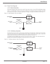
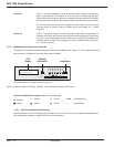
1.4.2.1 Normal Operation
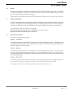
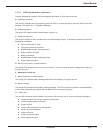
During normal operation, power flows from the main AC input source (mains 1) into the UPS rectifier/battery charger
section. The rectifier/battery charger converts the AC voltage to DC, maintains the charge of the battery, and feeds
the DC power to the inverter. The inverter regenerates AC voltage, and supplies the attached load. See Figure 1-5.
Figure 1-4: Normal Operation, Power Flow Diagram.
1.4.2.2 On-Battery Operation
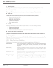
If the main AC input source (mains 1) fails or goes out of tolerance, the charger stops. Power flows from the battery
to the UPS inverter, which in turn supplies the attached load. When the main AC input source (mains 1) returns, the
charger restarts automatically and the UPS resumes its normal operation. See Figure 1-6.
If the battery becomes depleted before the main AC input source (mains 1) returns, the inverter stops and the
attached load is transferred to the bypass AC input source (mains 2) if it is available.
Figure 1-5: On-Battery Operation, Power Flow Diagram.
Bypass AC input
(mains 2)
Main AC input
(mains 1)
Rectifier/battery
charger
Inverter
Battery
Static switch
Attached
load(s)
Bypass AC input
(mains 2)
Main AC input
(mains 1)
Rectifier/battery
charger
Inverter
Battery
Static switch
Attached
load(s)