


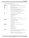


I: Battery discharged
This orange LED indicates that the battery has reached the end of its autonomy, shutting down the inverter.
J: Inverter desynchronized
This orange LED indicates that the inverter is not synchronized with the bypass AC input (mains 2).
K:Transfer fault
This red LED indicates a transfer fault, which may be one or more of the following conditions:
◗ Inverter output static switch fault
◗ Static switch over-temperature
◗ Static switch power supply fault
◗ Transfer control board fault
◗ Power supply board fault
L: Overload
This orange LED indicates an alarm condition resulting from one or more of the following conditions:
◗ Inverter current above rating
◗ Output current above rating
◗ Inverter and/or static switch shutdown due to excessive load current
M: Bypass AC input (mains 2) outside tolerance
This orange LED indicates that the bypass AC input (mains 2) voltage and/or frequency are too high or too low.
N: Maintenance position
This orange LED indicates that circuit breakers QF1, Q4S, Q5N, or Q3BP are set to the maintenance position. The
UPS is not available for load protection.
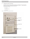
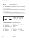
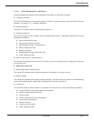
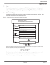
1.5.3.2 Hidden Panel Lower Pushbuttons
Following are brief descriptions of the function of the hidden panel pushbuttons. See Figure 1-9.
Test connector (port) This 9-pin connector is reserved for service. It is used to connect the cabinet
to a computer, allowing system calibration, personalization, and computer-aided
diagnostics.
Clear fault log Pressing this pushbutton clears the alarms stored in memory, allowing the unit to
restart. Memorized alarms cannot be cleared until the condition causing the alarm
has been corrected.
Audible alarm reset Pressing this pushbutton stops the audible alarm. Should a new fault condition at a
higher alarm level occur, the alarm will sound again.
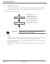
Battery charge cycle (pushbutton #1) Pressing this pushbutton begins a battery charging cycle. After the
cycle is complete, the rectifier/battery charger returns to float charge levels on the
battery. The battery charge cycle is not applicable to sealed lead-acid battery instal-
lations.
Introduction
EPS 7000 Single Module
page 1 — 12