


Introduction
page 1 — 3
Users Manual
1.4 Specifications, Circuit Breakers and Powerflow Diagrams
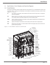
1.4.1 Circuit Breakers
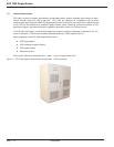
EPS 7000 circuit breakers (except the battery disconnect circuit breaker QF1) are located behind the doors of the
Input/Output cabinet. Following is a brief description of the available circuit breakers and contacts, and their function
(Figures 1-2, 1-3, and 1-4).
Q1 Input isolation circuit breaker, used to isolate the UPS from the main AC input (mains 1) and provide
input current protection.
QF1 Battery disconnect circuit breaker, external to the UPS, used to disconnect the battery from the UPS.
QF1 provides isolation and protection between the UPS and its battery system.
Q3BP (optional) Maintenance bypass circuit breaker, used to supply the attached load via the bypass source
while the UPS is being serviced.
Q5N Optional UPS isolation circuit breaker, used to isolate the UPS module from the attached load.
Q4S Bypass input circuit breaker; it is used to isolate the UPS from the bypass input (mains 2) source and
provide back-feed protection.
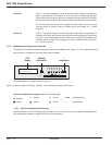
Figure 1-2: Circuit Breaker Locations on the EPS 7000.
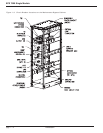
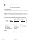
MODEM AND PWR
SUPPLY (OPTION)
BYPASS
STATIC
SWITCH
RECTIFIER
OUTPUT
STATIC
SWITCH
SERIES
FILTER
CHOKES
CONTROL
FUSES
Q1
INPUT CB
Q4S
BYPASS CB
INPUT
FUSES
MULTI-SLOT
(OPTION)
BLOWERS (4X)
BLOWERS (4X)
BLOWERS (3X)
RAUZ2 PCA (OPT)
RAUZ PCA
IBEZ PCA
OBEZ PCA
INVERTERS (6X)
DC CAPS
BAIZ1 PCA
TREZ PCA
SSSZ PCA
ALBZ PCA
EPOZ PCA
ACOZ PCA
ACUZ PCA
ARUZ PCA
OUTPUT XFMR
(BEHIND PANEL)
CARD CAGE
ALEZ PCA
AROZ—US PCA
CROZ—US PCA
CRIZ—US PCA
SRIZ PCA
GTCZ—7000 PCA
GT2Z—7000 PCA (OPT.)
INPUT FILTER (3X)
OUTPUT FILTER (4X)
FAN XFMRS
GUI POWER SUPPLY
OUTPUT FUSES
INPUT FILTER FUSES